
A kind of uninterruptible power supply and dc-dc converter

A DC-DC, converter technology, applied in the field of uninterruptible power supply, can solve the problems of high cost, low withstand voltage, large loss, etc., and achieve the effect of less components, improved performance, and low cost

Active Publication Date: 2016-06-29
HUAWEI DIGITAL POWER TECH CO LTD
View PDF2 Cites 0 Cited by
  • Summary
  • Abstract
  • Description
  • Claims
  • Application Information

AI Technical Summary

Problems solved by technology

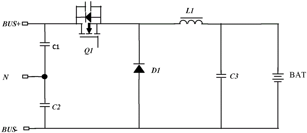
[0015] The disadvantages of this topology are: the input is connected to BUS+ and BUS-, and the input voltage is relatively high, resulting in a high withstand voltage for device selection in the BUCK topology, resulting in high cost, large loss, and low efficiency.
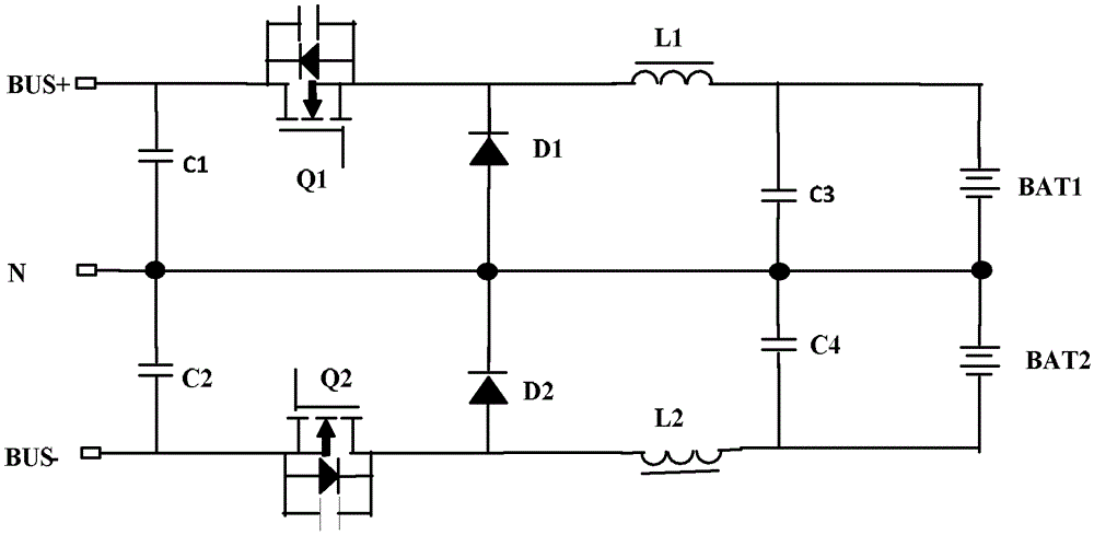
[0026] The advantage of this topology compared to single BUCK is: the input is connected to the BUS+, BUS- and N lines, the input voltage is low, and the devices in the BUCK topology can choose devices with low withstand voltage; but the disadvantage of this topology is: two sets are required The BUCK circuit has many devices, and the battery also needs two sets (BAT1 and BAT2), and the cost is relatively high; in addition, when the BUS voltage is low, it cannot meet the demand for charging the battery. , or between BUS- and N line) when the voltage is lower than the battery voltage, the battery cannot be charged
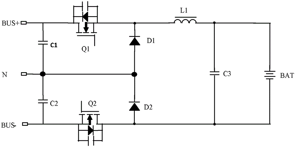
[0036] The disadvantage of this topology is: the negative terminal of BAT is connected to Q2, which is easily interfered by the high-frequency switching wave of Q2, and the N line also has the interference of high-frequency switching wave
This will affect the performance of the battery and the electromagnetic compatibility of the entire circuit

Method used


Image

  • A kind of uninterruptible power supply and dc-dc converter
  • A kind of uninterruptible power supply and dc-dc converter
  • A kind of uninterruptible power supply and dc-dc converter

Examples


Embodiment 1

[0093] see Figure 5 , which is a schematic diagram of Embodiment 1 of the DC-DC converter provided by the present invention.

[0094] The DC-DC converter provided in this embodiment includes: a first capacitor C1, a second capacitor C2, a third capacitor C3, a first switching tube Q7, a second switching tube Q8, a first inductor L5, a second inductor L6, the third switch tube and the fourth switch tube;

[0095] The positive bus BUS+ is connected to the first node a through the first switching tube Q7, and the negative bus BUS- is connected to the second node b through the second switching tube Q8;

[0096] The two ends of the first capacitor C1 are respectively connected to the BUS+ and the N line; the two ends of the second capacitor C2 are respectively connected between the BUS- and the N line;

[0097] The third switch tube is connected between the first node a and the N line;

[0098] The fourth switch tube is connected between the second node b and the N line;

[00...

Embodiment 2

[0110] see Figure 7 , which is a schematic diagram of Embodiment 2 of the DC-DC converter provided by the present invention.

[0111] In the DC-DC converter provided in this embodiment, the first inductor L5 and the second inductor L6 are integrated together, as Figure 7 L5 and L6 shown. In this way, the volume of the inductor can be reduced and the cost can be reduced.

[0112] It should be noted that when L5 and L6 are integrated together, the third capacitor C3 is connected in parallel to both ends of the battery BAT.

Embodiment 3

[0114] see Figure 8 , which is a schematic diagram of Embodiment 3 of the DC-DC converter provided by the present invention.

[0115] This embodiment and Figure 7 The difference of the provided second embodiment is that the third switch tube and the fourth switch tube are controllable tubes, such as Figure 8 Q9 and Q10 in.

[0116] Figure 8 In the DC-DC converter provided by the illustrated embodiment, the input and output can be bidirectionally converted to each other. For example, BUS+ and BUS- can be used as the input terminal of the converter, and BAT can be used as the output terminal of the converter; in addition, BAT can be used as the converter The input terminals of BUS+ and BUS- can be used as the output terminals of the converter.

[0117] It should be noted that the function of C3 in all the above embodiments is output filtering. When the circuit works in continuous mode, the function of C3 is only output filtering; when the circuit works in discontinuous m...


PUM


Abstract

The present invention provides a UPS and a DC-DC converter, wherein the UPS includes: a rectifier, an inverter and a DC-DC converter; the input terminals of the DC-DC converter are connected to BUS+, BUS- and N lines, so that the input voltage Low, the devices in the DC-DC converter can choose devices with low withstand voltage; and the load in the DC-DC converter is not directly connected to the second switch tube, but connected to the second switch tube through the second inductor, so , the high-frequency switching wave on the second switching tube will not affect the load, which will improve the performance of the load and the anti-electromagnetic interference capability of the entire circuit. Moreover, the DC-DC converter provided by the present invention is not as complex in structure as the dual BUCK topology in the prior art. Therefore, compared with the dual BUCK topology, the present DC-DC converter has fewer components and lower cost.

Description

technical field [0001] The present invention relates to the technical field of uninterrupted power supplies, in particular to an uninterrupted power supply (UPS, Uninterrupted Power Supply) and a DC-DC (Direct Current-Direct Current) converter. Background technique [0002] Online UPS has been widely used in various power supply occasions. This UPS circuit generally includes three parts: [0003] The first part is the AC-to-DC conversion circuit, that is, the rectifier circuit; [0004] The second part is the inverter circuit of DC to AC; [0005] The third part is a DC-to-DC circuit that converts the battery voltage into the DC voltage required by the second part of the inverter circuit; [0006] The UPS charger is a charging device for charging the battery connected to the UPS in the third part. [0007] At present, in the design of UPS chargers, two methods are generally adopted: [0008] One is to use an isolation method, such as a commonly used flyback, forward or o...

Claims


Application Information

Patent Timeline
Patent Type & Authority Patents(China)
IPC IPC(8): H02J9/04H02M3/10
CPCH02J9/062H02M3/1584H02J9/063H02M3/1586H02M1/4225H02J9/04
Inventor 刘培国费珍福周亚男
Owner HUAWEI DIGITAL POWER TECH CO LTD
Learn More