Mobile floor cleaning device having noise insulation

A ground cleaning and equipment technology, applied in cleaning equipment, manual floor scrubbing machinery, cleaning machinery, etc., can solve problems such as noise, achieve the effects of reducing noise, reducing flow resistance, and generating less noise

Inactive Publication Date: 2013-07-17
ALFRED KARCHER GMBH & CO KG
View PDF4 Cites 7 Cited by
  • Summary
  • Abstract
  • Description
  • Claims
  • Application Information

AI Technical Summary

Problems solved by technology

This can cause some noise

Method used


Image

  • Mobile floor cleaning device having noise insulation
  • Mobile floor cleaning device having noise insulation
  • Mobile floor cleaning device having noise insulation

Examples


Embodiment Construction

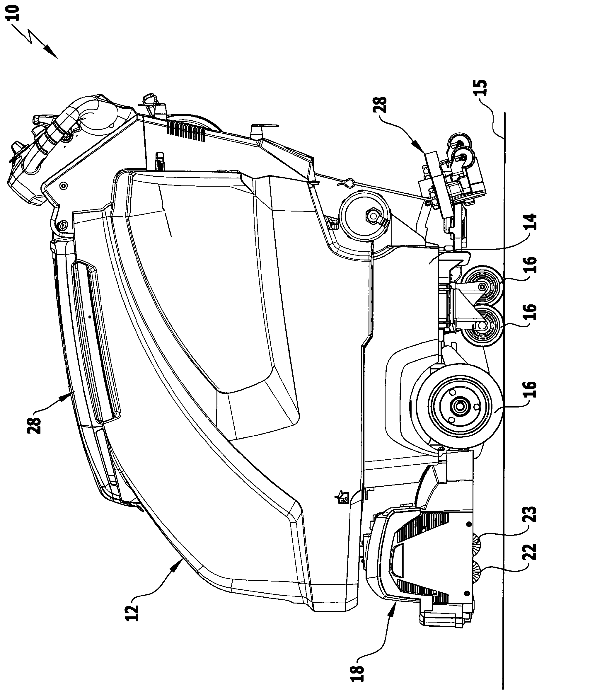
[0038] The figure shows schematically a floor-cleaning device according to the invention in the form of a floor scrubber 10 with which a floor 15 can be cleaned. The scrubber 10 has a one-piece hollow body 12 made of plastic material and placed on a travel mechanism 14 . The running wheels 16 are rotatably mounted on the running gear, so that the scrubber 10 can be moved along the floor 15 . Below the hollow body 12 a brush head 18 is held in front of the carriage 14 and behind the carriage 14 a suction rod 20 is arranged. The brush head 18 has cleaning tools in the form of two rotatably mounted first brush rollers 22 and second brush rollers 23 on its underside and can be removed from it. figure 1 From the raised position shown, the lowering to the floor 15 is started to clean the floor 15 .

[0039] The suction rod 20 generally comprises a suction lip which is not shown in the drawings for a clear overview and can be obtained from it. figure 1 The raised position shown is...


PUM


Abstract

The invention relates to a mobile floor cleaning device (10) comprising at least one cleaning tool (22, 23), a cleaning liquid tank (36), a dirt liquid tank (26) and a suction unit (32). In order to further develop the floor cleaning device (10) such that it has a reduced noise emission, a first recess (30) is formed into the tank wall of the cleaning liquid tank (36) or the dirt liquid tank (26), the suction unit (32) being arranged in said recess which is covered by a first cover element (51). According to the invention, the tank wall and / or the first cover element (51) form at least one air guide channel (76, 79, 83) extending from the first recess (30) to an opening (77, 80, 84).

Description

technical field [0001] The invention relates to a mobile floor cleaning device with at least one cleaning tool for cleaning the floor, a cleaning liquid tank and a dirt liquid tank and a suction unit for sucking up cleaning liquid applied to the floor and Transfer cleaning fluid to dirty fluid container. Background technique [0002] Such floor cleaning devices are known, for example, in the form of floor scrubbers, in which one or more floor scrubbing brushes are used as cleaning tools, which contact the floor to be cleaned and clean it with the aid of a cleaning fluid. The cleaning fluid is stored in the cleaning fluid tank and applied to the floor in the area of ​​the scrub brushes. The applied cleaning fluid together with the removed dirt is then sucked up from the floor by the suction unit and transferred to the dirt tank. [0003] The suction unit usually has a suction turbine, which is driven by an electric motor in order to generate the vacuum required to suck up t...

Claims


Application Information

Patent Timeline
Patent Type & Authority Applications(China)
IPC IPC(8): A47L11/30A47L11/40
CPCA47L11/4097A47L11/4013A47L11/302A47L11/4083
Inventor 弗兰克·农嫩曼伯恩哈特·毛雷尔斯特芬·库尔茨
Owner ALFRED KARCHER GMBH & CO KG
Why Eureka
Try Eureka