Cutting and detection method of full-automatic surface mount tomography (SMT) template cutting and detection integrated system

A detection method and fully automatic technology, applied in welding equipment, laser welding equipment, metal processing equipment and other directions, can solve the problems of low detection efficiency and accuracy, unreliable SMT template, etc., to improve detection efficiency and accuracy, The effect of saving production cost and good technical effect

Active Publication Date: 2013-07-24
KUNSHAN THETA MICRO
View PDF6 Cites 7 Cited by
  • Summary
  • Abstract
  • Description
  • Claims
  • Application Information

AI Technical Summary

Problems solved by technology

[0005] The technical problem to be solved by the present invention is the unreliability of manual detection of the SMT template existing in the prior art after cutting, and the problem of low detection efficiency and accuracy. The present invention provides a new high-efficiency fully automatic SMT template cutting and The cutting and detection method of the integrated detection system, the high-efficiency automatic SMT template cutting and detection integrated system has the advantages of high detection reliability of the SMT template after cutting, and at the same time improves the detection efficiency and accuracy

Method used


Image

  • Cutting and detection method of full-automatic surface mount tomography (SMT) template cutting and detection integrated system
  • Cutting and detection method of full-automatic surface mount tomography (SMT) template cutting and detection integrated system
  • Cutting and detection method of full-automatic surface mount tomography (SMT) template cutting and detection integrated system

Examples


Embodiment 1

[0030] A cutting and testing method of an integrated automatic SMT template cutting and testing system comprises the following steps:

[0031] a) The CCD linear scanning component moves to the cutting area in the X and Y directions, and to the scanning position, while the upper beam moves to the non-cutting area;

[0032] b) Press down on the light box above the beam, clamp the cut steel sheet with the upper glass surface of the CCD linear scanning component below, and enter the scanning state for scanning detection;

[0033] c) The cutting and scanning files, position, direction, front and back judgment work is automatically completed by the main control computer;

[0034] d) After scanning, the light box moves up, and the CCD scanning component moves down. After the cutting is completed, the waste vacuum device automatically exits the machine to clean up the waste;

[0035] e) After the waste dust suction device cleans up the waste residue, it returns to the main body of th...

Embodiment 2

[0041] A cutting and detection method of a fully automatic SMT template cutting and detection integrated system, the steps of which are the same as in Example 1.

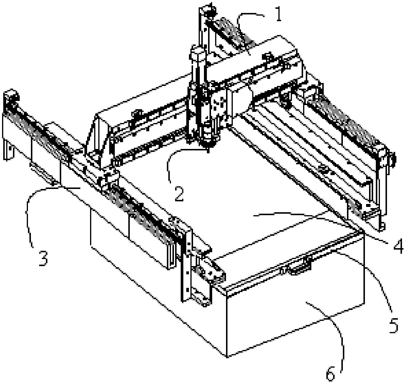
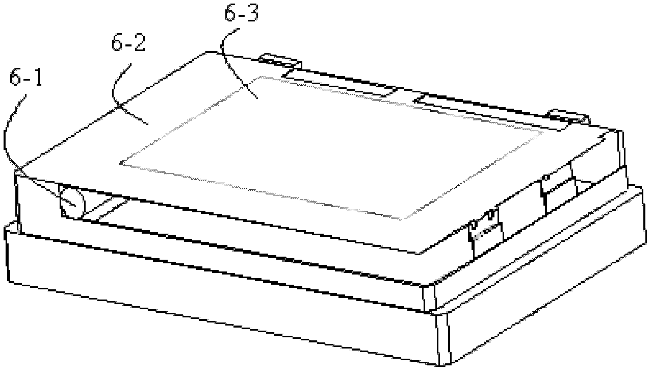
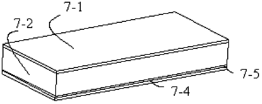
[0042] Fully automatic SMT template cutting and testing integrated system, including cutting head, X-direction moving beam, Y-direction moving beam, steel sheet stretching mechanism, waste dust suction part, CCD linear scanning component and main control computer, the cutting head is located in X direction On the moving beam, the waste dust suction part is located under the steel sheet stretching mechanism, the CCD linear scanning component is located under the waste dust suction device, a light box is installed above the X-direction moving beam, the CCD linear scanning component has a glass surface, and the main computer controls the cutting head. , The movement of CCD linear scanning components. Three-dimensional light box image 3 As shown, 7-1 is a light box cover plate; 7-2 is a longitudinal support plate; 7-3...

Embodiment 3

[0046] A cutting and testing method of an integrated automatic SMT template cutting and testing system comprises the following steps:

[0047] a) The CCD linear scanning component moves to the cutting area in the X and Y directions, and to the scanning position, while the upper beam moves to the non-cutting area;

[0048] b) Press down on the light box above the beam, clamp the cut steel sheet with the upper glass surface of the CCD linear scanning component below, and enter the scanning state for scanning detection;

[0049] c) The cutting and scanning files, position, direction, front and back judgment work is automatically completed by the main control computer;

[0050] d) After scanning, the light box moves up, and the CCD scanning component moves down. After the cutting is completed, the waste vacuum device automatically exits the machine to clean up the waste;

[0051] e) After the waste dust suction device cleans up the waste residue, it returns to the main body of th...


PUM


Abstract

The invention relates to a cutting and detection method of a full-automatic surface mount tomography (SMT) template cutting and detection integrated system, which mainly solves the unreliability problem of the manual detection in the prior art after an SMT template is cut. The invention adopts a technical scheme that a cutting and detection method of a full-automatic SMT template cutting and detection integrated system is provided. The cutting and detection integrated system comprises a cutting head, an X-direction mobile crossbeam, a Y-direction mobile crossbeam, a steel plate stretching mechanism, a waste dust adsorption part and a charge coupled device (CCD0 linear scanning assembly, wherein the cutting head is arranged on the X-direction mobile crossbeam, the waste dust adsorption part is arranged below the steel plate stretching mechanism, the CCD linear scanning assembly is arranged below the waste dust adsorption device, a lamp house is arranged above the X-direction mobile crossbeam, and the CCD linear scanning assembly is provided with a glass surface. The technical scheme can be used for well solving the problem, and can be used for the integrated system for cutting and detecting the SMT template and particularly for the equipment system for cutting and detecting an SMT laser template.

Description

[0001] technical field [0002] The invention relates to a cutting and testing method for an integrated system of SMT template cutting and testing, in particular to an equipment system applied to SMT laser template cutting and testing. Background technique [0003] At present, the SMT template laser cutting technology is widely used. After the template is cut by using the moving beam high-speed cutting, the template often has defects of holes or few holes. Nowadays, manual inspection is generally used. For templates with a large number of holes and high density, there are often omissions, and human factors have become an important factor affecting quality reliability. After the cutting is completed, it is a stable and reliable method to scan the template with a linear CCD detection device, and then perform image processing and recognition comparison. If a leak occurs, it needs to return to the cutting equipment for alignment, and then repair the hole. If it is porous, it w...

Claims


Application Information

Patent Timeline
Patent Type & Authority Applications(China)
IPC IPC(8): B23K26/36B23K26/16B23K26/42B23K26/38B23K26/70
Inventor 魏志凌宁军龚关
Owner KUNSHAN THETA MICRO
Why Eureka
Try Eureka