
Combined double-shaft-shoulder friction stir welding fixture

A friction stir welding and double-shoulder technology, which is applied in manufacturing tools, welding equipment, welding equipment, etc., can solve the problems of affecting the welding process, affecting the welding quality, and the stirring needle is easy to break, and achieves high practicability and simple structure. Effect

Inactive Publication Date: 2013-07-24
JIANGSU UNIV OF SCI & TECH
View PDF5 Cites 4 Cited by
  • Summary
  • Abstract
  • Description
  • Claims
  • Application Information

AI Technical Summary

Problems solved by technology

[0003] The structure of the double-shaft-shouldered friction stirring head makes the stirring needle bear a great tension. At the same time, due to the travel resistance and lateral pressure in the welding direction and transverse direction, the stirring needle is easy to break, which not only affects the welding process, but also affects the welding process. Therefore, the force borne by the stirring needle is worthy of research and exploration; compared with the traditional friction stir welding fixture, the double-shouldered friction stir welding fixture not only needs to fix the material to be welded, but also needs to have sufficient internal space for easy installation Lower shoulder: the current domestic and foreign research on friction stir welding of double-shaft shoulders has just started, and the fixtures used are all simple pads, pressure blocks and calipers, which is not conducive to conveniently extracting the travel resistance and lateral pressure. Therefore, it is necessary to develop a set of fixtures that can detect the travel resistance and lateral pressure of double-shaft shoulder friction stir welding.

Method used


Image

  • Combined double-shaft-shoulder friction stir welding fixture
  • Combined double-shaft-shoulder friction stir welding fixture
  • Combined double-shaft-shoulder friction stir welding fixture

Examples


Embodiment Construction

[0017] Below in conjunction with accompanying drawing and specific embodiment, further illustrate the present invention, should be understood that these embodiments are only for illustrating the present invention and are not intended to limit the scope of the present invention, after having read the present invention, those skilled in the art will understand various aspects of the present invention Modifications in equivalent forms all fall within the scope defined by the appended claims of this application.

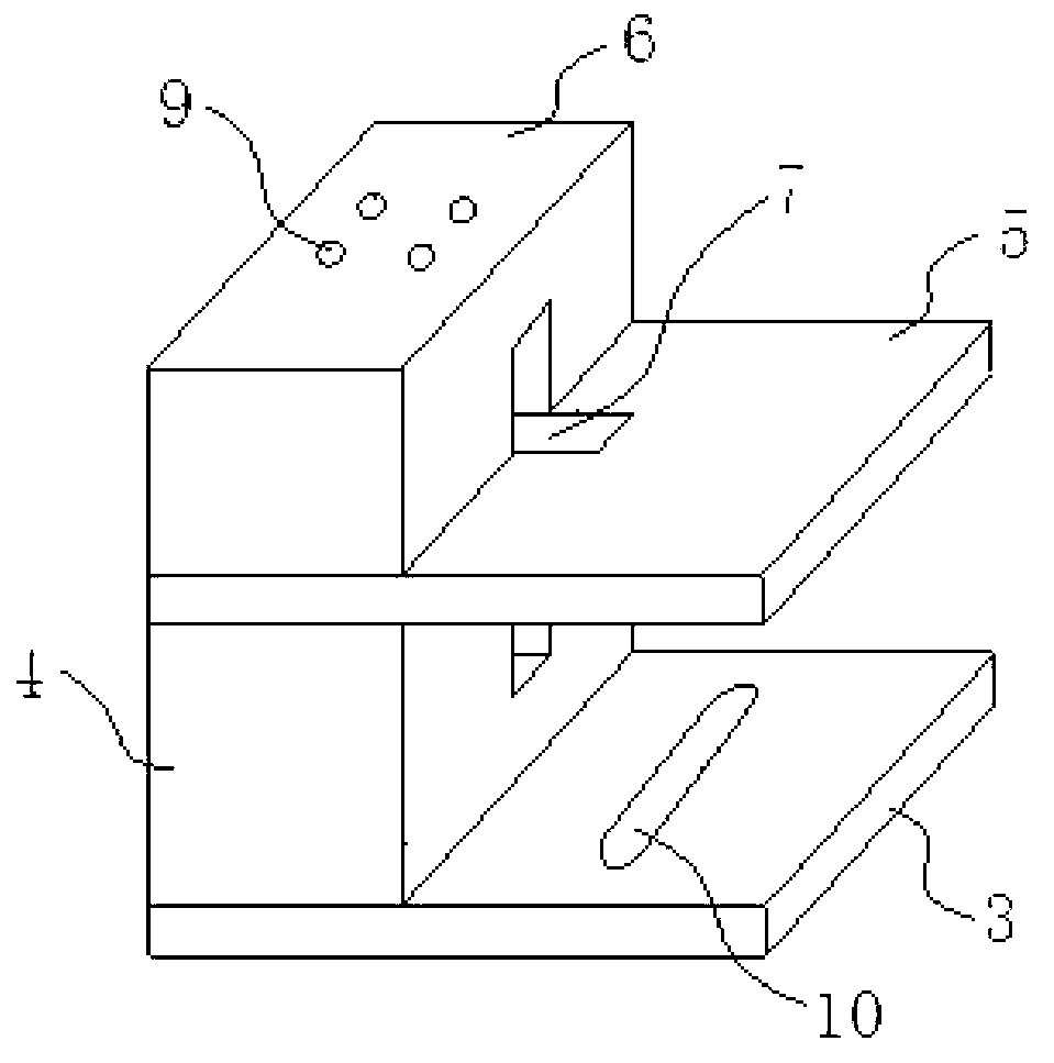
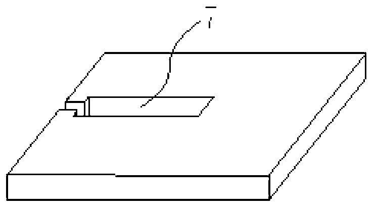
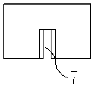
[0018] Such as Figure 1-5 As shown, a combined double-shaft shoulder friction stir welding fixture is composed of a clamping module and a heat sink module. According to different application requirements, the fixture material can be ordinary carbon steel or high alloy steel. The clamping module consists of a fixed plate, a lower platform, a support plate and an upper platform that are sequentially connected from bottom to top, wherein the lower platform, the support pla...


PUM


Abstract

The invention discloses a combined double-shaft-shoulder friction stir welding fixture which comprises a clamping die block and a heat sink die block. The clamping die block comprises a fixed plate, a lower platform, a supporting plate and an upper platform which are fixedly connected from bottom to top in sequence. The supporting plate is provided with an exposed bearing end corresponding to the upper platform and the lower platform. The heat sink die block is a cooling panel and is placed on the bearing end of the supporting plate. The combined double-shaft-shoulder friction stir welding fixture is capable of meeting clamping requirements of trial panels with different thicknesses and different sizes, prevents the trial panels from distorting and moving up and down in the welding process due to axial acting force of a stir-welding head, is capable of achieving a test of extrusion force of the stir-welding head to a workpiece, and is simple in structure and strong in practicality.

Description

technical field [0001] The invention belongs to the technical field of technical material processing and welding, and in particular relates to a clamping tool for a welded workpiece of a friction stir welding machine. Background technique [0002] Double-shoulder friction stir welding is a new type of friction stir welding technology. During the welding process, the workpiece is clamped by the upper and lower shoulders. The lower shoulder replaces the backing plate device of conventional friction stir welding, so it does not need welding equipment to provide a lot At the same time, this friction stir head structure makes the upsetting force of the upper and lower shoulders equal in opposite directions, and the resultant force on the entire workpiece in the direction perpendicular to the plate is zero, which is very suitable for the welding of hollow components. Therefore, this method It has broad application prospects in shipbuilding, aerospace, rail transit and other fields...

Claims


Application Information

Patent Timeline
Patent Type & Authority Applications(China)
IPC IPC(8): B23K37/04B23K20/12
Inventor 陈书锦杨代立芦笙卢阿丽
Owner JIANGSU UNIV OF SCI & TECH
Learn More