Optical fiber preform cutting device

A technology of optical fiber preform and cutting device, which is applied in the direction of glass cutting device, manufacturing tools, glass manufacturing equipment, etc. It can solve the problem that the rotation speed of optical fiber preform is difficult to coordinate with the cutting sheet, and the enlightenment and influence of sewage control are not given. Problems such as the cross-section quality of optical fiber preform rods, to achieve the effect of improving cutting efficiency, protecting the environment, and reasonable structure

Active Publication Date: 2017-08-18
QINGHAI ZHONGLI OPTICAL FIBER TECH CO LTD
View PDF16 Cites 1 Cited by
  • Summary
  • Abstract
  • Description
  • Claims
  • Application Information

AI Technical Summary

Problems solved by technology

[0006] Although the above-mentioned CN203794783U can realize the technical effect recorded in paragraph 0016 of its description: by setting a bracket and a pair of rollers on the bracket, the optical fiber preform can be cut Make its axis vertical to the slices of the cutting machine to avoid cracks and chipping during cutting, but there are the following shortcomings: First, since the operator must reliably pinch the prefabricated optical fiber during the cutting process of the cutting sheet The rod must rotate the optical fiber preform, so the operator's work intensity is high; secondly, because the rotation of the optical fiber preform is controlled by the operator and the movement of the cutting piece is controlled by machinery, the rotation speed of the optical fiber preform It is difficult to coordinate with the cutting sheet, which will not only affect the cutting efficiency, but also affect the section quality of the cut optical fiber preform. For example, during the cutting process, the optical fiber preform will inevitably vibrate or move on the roller, unless The operator has enough control over the optical fiber preform, but it is difficult to turn it with one hand; third, because the surface of the optical fiber preform produced by the OVD method has a micro-helical shape and a diameter difference when there is no extension or no extension , so it is often impossible to cut without the use of a reasonable mechanical clamping mechanism, so the cutting of this type of optical fiber preform is critical; Fourth, although the patent gives the inspiration of the cooling water pipe, it does not give Enlightenment of Controlling the Sewage Leading from the Cooling Water Pipe and Flowing from the Cutting Part

Method used


Image

  • Optical fiber preform cutting device
  • Optical fiber preform cutting device

Examples


Embodiment Construction

[0022] In order to understand the technical essence and beneficial effects of the present invention more clearly, the applicant will describe in detail the following examples, but the descriptions of the examples are not intended to limit the solutions of the present invention. Equivalent transformations that are only formal but not substantive should be regarded as the scope of the technical solution of the present invention.

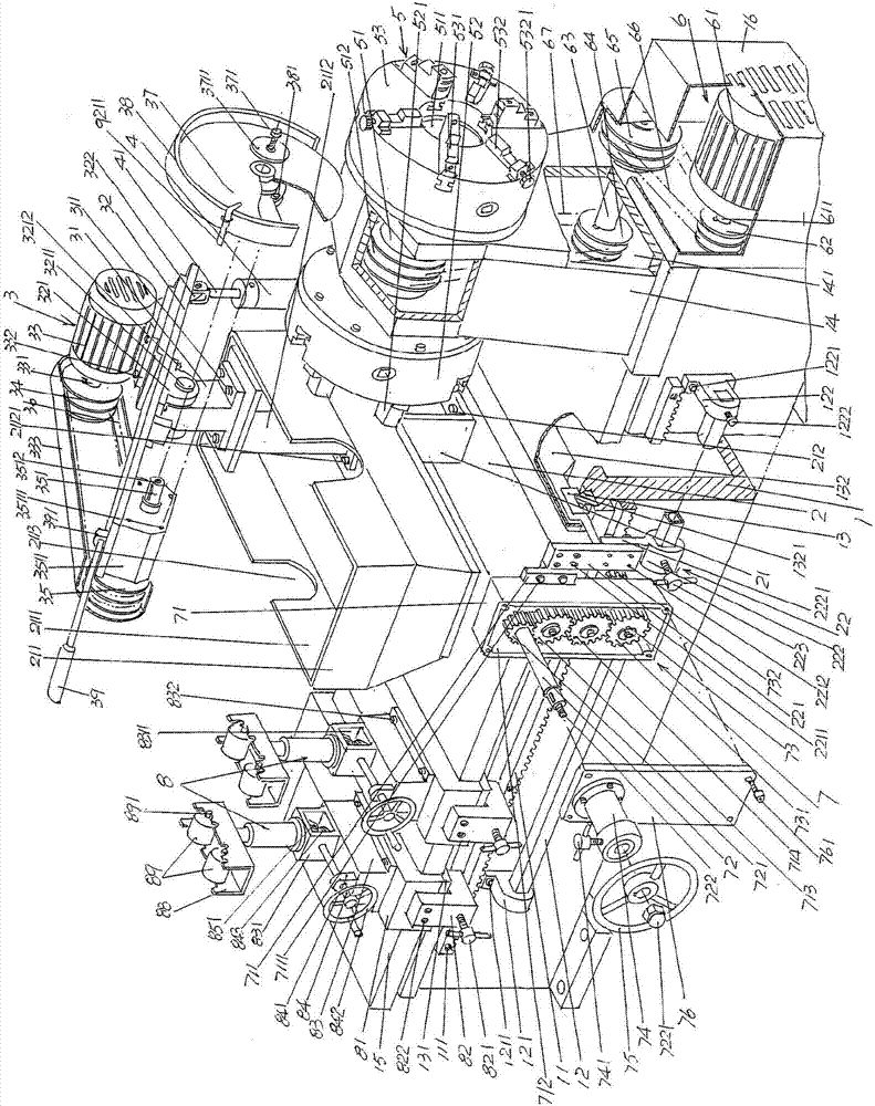
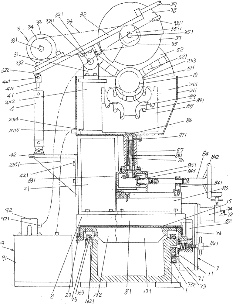
[0023] In the following descriptions, all concepts related to directionality or orientation of up, down, left, right, front and back are based on figure 1 The position states shown are for reference, for example figure 2 The front side of the state shown is essentially figure 1 The right side of the state shown, so it cannot be understood as a special limitation on the technical solution provided by the present invention.

[0024] See figure 1 , shows a machine bed 1 whose cross-section or cross-sectional shape is generally U-shaped, and a rack 11 ...


PUM


Abstract

An optical fiber preform cutting device comprises a machine tool bed body, an upper drag plate, a preform cutting mechanism, a cutting motor fixed plate connection acting cylinder, a preform clamping mechanism, a power transmission mechanism, an upper drag plate left and right displacement driving mechanism and a preform auxiliary holding and lifting mechanism, wherein the front side of the machine tool bed body is provided with a rack; the top of the front and the rear sides of the machine tool bed body is provided with a bed body guide rail; the upper part of the right end of the machine tool bed body is provided with a bed head box; a left lower tray plate and a right lower drag plate are arranged on the bed body guide rail; the upper drag plate is fixed to the right lower tray plate, and a bracket is arranged above the upper drag plate; the top of the bracket is provided with a cooling water collecting tank; a cutting mechanism bearing seat is arranged in a cavity of the water collecting tank; the end surface of the front end of the upper drag plate is provided with an upper tray plate locking mechanism; the preform cutting mechanism is supported on the cutting mechanism bearing seat; the cutting motor fixed plate connection acting cylinder is supported on the bracket; the preform clamping mechanism is supported on the bed head box; the power transmission mechanism is fixed to the end surface of the right end of the machine tool bed body; the upper drag plate left and right displacement driving mechanism is fixed to the upper tray plate locking mechanism; the preform auxiliary holding and lifting mechanism is arranged on a left lower tray plate, and locked or unlocked with the front side of the machine tool bed body. The device has the advantages that the operation strength is reduced; the cutting efficiency is improved; the case of being picky on the optical fiber preform type is avoided; the environment is protected.

Description

technical field [0001] The invention belongs to the technical field of auxiliary mechanical equipment in optical fiber production, and in particular relates to an optical fiber preform rod cutting device. Background technique [0002] As is known in the industry, in the process of optical fiber production, cutting devices are required in the processes of slitting optical fiber preforms, welding tail handles before drawing preforms, and removing the head and tail cones of semi-finished preforms. In each slitting process, the requirements for the section quality of the preform after slitting are quite strict. For example, if the section after slitting is not smooth, it is difficult to guarantee the welding quality of the tail shank or even the tail shank cannot be welded. [0003] Since the optical fiber preform cutting device is non-standard equipment, it is mostly designed and manufactured by the optical fiber manufacturer. As far as the applicant knows, there are mainly th...

Claims


Application Information

Patent Timeline
Patent Type & Authority Applications(China)
IPC IPC(8): C03B33/06C03B37/012
CPCC03B33/06C03B37/012Y02P40/57
Inventor 窦生孝马晓光白玉谭宋建鹏王生龙
Owner QINGHAI ZHONGLI OPTICAL FIBER TECH CO LTD
Why Eureka
Try Eureka