Dual-opening magnetic circuit iron core device body clamping device used for electrical equipment

A technology for power equipment and clamping devices, applied in circuits, transformer/inductor magnetic cores, electrical components, etc., can solve the problems of application of clamping devices without iron cores, and achieve the effect of strong adaptability and satisfying clamping requirements

Active Publication Date: 2018-12-04
STATE GRID CHONGQING ELECTRIC POWER +1
View PDF8 Cites 1 Cited by
  • Summary
  • Abstract
  • Description
  • Claims
  • Application Information

AI Technical Summary

Problems solved by technology

[0004] As for the double-opening combined core, since this is a new structure core, there is no mature core clamping device applied at present.

Method used


Image

  • Dual-opening magnetic circuit iron core device body clamping device used for electrical equipment
  • Dual-opening magnetic circuit iron core device body clamping device used for electrical equipment
  • Dual-opening magnetic circuit iron core device body clamping device used for electrical equipment

Examples


Embodiment 1

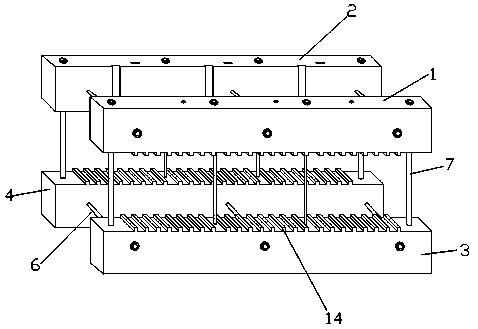
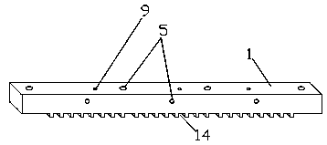
[0029] Figure 4 and Figure 5 Shown is a schematic diagram of the assembly structure between the five-column combined iron core and the clamping device. The high-voltage upper clamp 1, the low-voltage upper clamp 2, the high-voltage lower clamp 3 and the low-pressure lower clamp 4 are clamped on the core body. On the coil, the vertical pull screw 7 connecting the high-voltage upper clamp 1 and the high-voltage lower clamp 3 and the low-voltage upper clamp 2 and the low-voltage lower clamp 4 is located in the interval formed between the coils, connecting the high-voltage upper clamp 1 The horizontal pull screw 6 between the low pressure upper clamp 2 and the high pressure lower clamp 3 and the low pressure lower clamp 4 is located in the "V" shaped opening formed on the five-column combined iron core 11. The screw rod 6 and the vertical pulling screw rod 7 can tightly clamp the five-column combined iron core with the high-voltage upper clamp 1 , the low-pressure upper clamp 2...

Embodiment 2

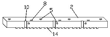
[0031] Figure 6 and Figure 7Shown is a schematic diagram of the assembly structure between the three-column combined iron core and the clamping device. The high-voltage upper clamp 1, the low-voltage upper clamp 2, the high-voltage lower clamp 3 and the low-pressure lower clamp 4 are clamped on the core body. On the coil, the vertical pull screw 7 connecting the high-voltage upper clamp 1 and the high-voltage lower clamp 3 and the low-voltage upper clamp 2 and the low-voltage lower clamp 4 is located in the interval formed between the coils, connecting the high-voltage upper clamp 1 The horizontal pull screw 6 between the low pressure upper clamp 2 and the high pressure lower clamp 3 and the low pressure lower clamp 4 is passed through the triangular hole formed on the three-column combined iron core 12. The screw rod 6 and the vertical pulling screw rod 7 can tightly clamp the five-column combined iron core with the high-voltage upper clamp 1 , the low-pressure upper clamp...


PUM


Abstract

The invention discloses a dual-opening magnetic circuit iron core device body clamping device used for electrical equipment. The device has a high-voltage upper clamping piece, a low-voltage upper clamping piece, a high-voltage lower clamping piece, and a low-voltage lower clamping piece made of a high-strength nonmetal insulating material. The high-voltage upper clamping piece, the low-voltage upper clamping piece, the high-voltage lower clamping piece, and the low-voltage lower clamping piece are connected together through a plurality of horizontal pulling screws and a plurality of verticalpulling screws, to form a rigid frame structure. The dual-opening magnetic circuit iron core device body clamping device used for electrical equipment adopts a nonmetal material as clamping components, and the screws on horizontal and vertical directions are used to form the rigid frame structure to clamp an iron core and a device body. In a device body leakage magnetic field environment, no lossis generated, and the device has enough mechanical strength and can satisfy clamping requirements of a dual-opening combined iron core device body. On the other hand, the clamping components in the structure can be designed in an adjusting manner according to size variation of a dual-opening combined iron core, and adaptability is good.

Description

technical field [0001] The invention relates to the field of electric equipment manufacturing, in particular to a double-opening magnetic circuit iron core body clamping device for electric equipment. Background technique [0002] At present, in power equipment, such as transformers and reactors, the clamping parts of the iron core body are made of steel materials, such as channel steel, which are used to clamp the iron core and compress the body coil; for example, the existing In the technology, the clamping method for the three-phase laminated iron core is to clamp through channel steel metal clamps (see the attached manual for details). Figure 8 ). [0003] Although steel structural parts have the advantage of good strength, their disadvantages are also very prominent. For example, in the leakage field of the iron core body, eddy current loss will be induced on the steel structural parts, which will cause local temperature rise and may damage the surrounding insulation. ...

Claims


Application Information

Patent Timeline
Patent Type & Authority Applications(China)
IPC IPC(8): H01F27/26
CPCH01F27/263H01F27/266
Inventor 韩宝家韩佳平韩宝华姚萍陈亮
Owner STATE GRID CHONGQING ELECTRIC POWER
Why Eureka
Try Eureka