
Automatic winding machine for sewing machine

An automatic thread winding and sewing machine technology, which is applied in the direction of bobbin winding in sewing machines, sewing equipment, sewing machine components, etc., can solve the problems of easy thread falling off, difficult to become larger, easy to be pulled off, etc., and achieve the effect that it is not easy to fall off

Pending Publication Date: 2018-04-13
上工缝制机械(浙江)有限公司
View PDF8 Cites 0 Cited by
  • Summary
  • Abstract
  • Description
  • Claims
  • Application Information

AI Technical Summary

Problems solved by technology

[0004] However, the above-mentioned wire winder has the following defects: 1. Since the size of the gap between the cutting knife and the winding liner in the above-mentioned wire winder is fixed, then, when the suture is thick, it may not be possible to ensure that the seam The thread is completely stuck into the above-mentioned gap, so that the clamping force on the suture is limited, and it is easy to be pulled off during the rotation of the thread; The force is small, and it is easy to be pulled off during the winding and rotating process, resulting in the suspension of automatic winding. It satisfies the requirements of automatic winding of sutures of different thicknesses; 2. The secant knife in the above thread winder is fixed on the winding liner by screws. Since the above secant knife is short, the space for its elastic deformation is extremely limited , That is to say, the gap between the secant knife and the winding liner is difficult to become larger, so the wire is not easy to be clamped and clamped, and the wire is easy to be pulled and easily fall off during the rotation and winding process

Method used


Image

  • Automatic winding machine for sewing machine
  • Automatic winding machine for sewing machine
  • Automatic winding machine for sewing machine

Examples


Embodiment Construction

[0031] The following are specific embodiments of the present invention and in conjunction with the accompanying drawings, the technical solutions of the present invention are further described, but the present invention is not limited to these embodiments.

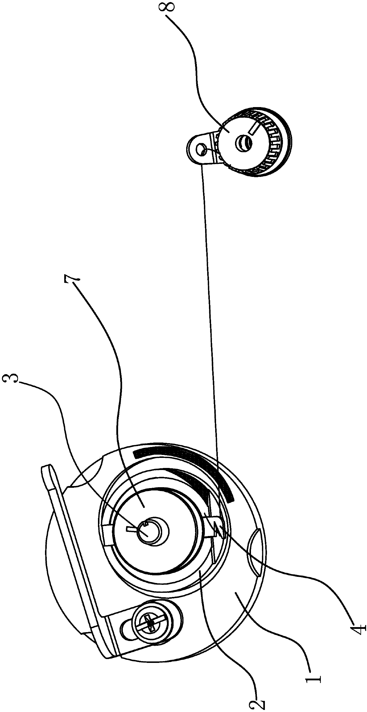
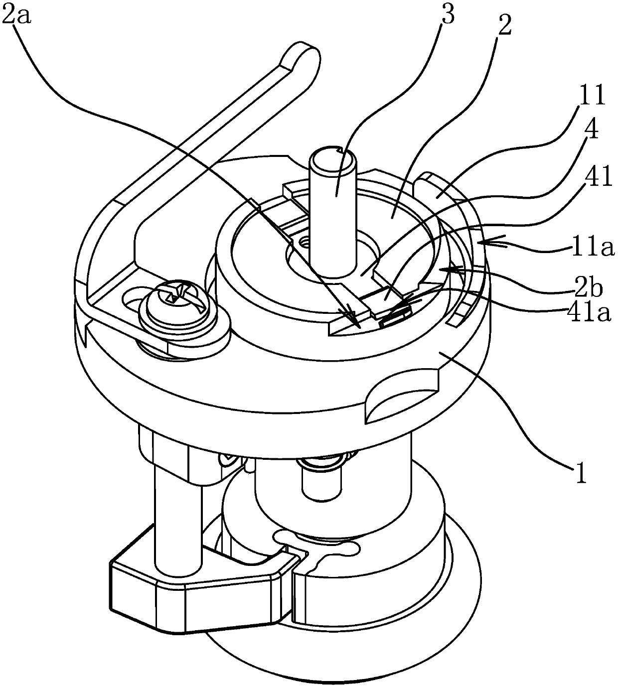
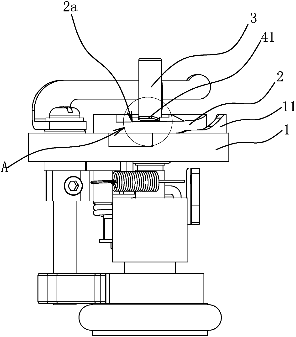
[0032] Such as figure 1 As shown, the suture is clamped on the bobbin winder through the thread gripper 8, and then the bobbin 7 is loaded on the bobbin winder to realize automatic winding. The thread winder can make the suture not easy to fall off during the thread winding process. Specifically, as figure 2 As shown, the structure of the automatic bobbin winder includes a bobbin seat 1, a cylindrical bobbin pad 2, a bobbin shaft 3 that can drive the bobbin pad 2 to rotate relative to the bobbin pad 1, and is fixedly connected to the bobbin pad 2. The secant knife 4, one end of the secant knife 4 is a secant portion 41 with a knife edge 41a on one side, the knife edge 41a is V-shaped and has an inclined downward guide s...


PUM


Abstract

The invention provides an automatic winding device for a sewing machine, and belongs to the technical field of sewing machines. The winding machine solves the problems of how to meet the clamping requirements of stitches different in thickness in the winding process and to tightly clamp the stitches. The winding device includes a winding base, a shuttle peg pad, a winding shaft and a thread cutter, wherein the winding shaft can drive the shuttle peg pad to rotate relative to the winding base, and the thread cutter is fixedly connected with the shuttle peg pad, one end of the thread cutter is provided with a thread cutting part with a knife edge, the winding base is provided with a thread clamping oblique plane opposite to the thread cutting part and oblique from bottom to top in the rotation direction of the shuttle peg pad, a thread clamping gap is left between the thread cutting part and the thread clamping oblique plane, and the width of the thread clamping gap is gradually reducedfrom one side, where the knife edge is located, of the thread cutting part to the other side of the thread cutting part in the rotation direction of the shuttle peg pad. Through the above design, thewinding device can be applied to clamping of the stitches different in size, the stitches different in thickness can be clamped under the thread cutter in the winding process, and the stitches can beclamped more tightly and not easy to fall off.

Description

technical field [0001] The invention belongs to the technical field of sewing machines and relates to an automatic thread winder for sewing machines. Background technique [0002] When the sewing machine is working, it is necessary to wind the thread on the bobbin and place it in the bobbin case to ensure the completion of the target requirements. In order to improve the winding efficiency, a winding device is added on the upper part of the machine, which can realize the function of winding while working. The thread winder on the current sewing machine is the whole assembly, and the mounting plate of the thread winder is fixed on the machine head with screws to realize the fixing of the thread winder. When the installed thread winder is working on the sewing machine, it will automatically drive the rotating shaft on the thread winder to rotate, and finally realize the function of automatic thread winding. [0003] For example, the Chinese patent [Application No.: 201610266...

Claims


Application Information

Patent Timeline
IPC IPC(8): D05B59/00
CPCD05B59/00
Inventor 杨锦阳潘灵刚李恩根陈亨敏阮玲斐余祥建
Owner 上工缝制机械(浙江)有限公司
Learn More