
Double-layer running urban rail transportation system

An urban rail transit and rail transit technology, applied in the field of urban rail transit system, can solve the problems of slow speed of ordinary public transport and unsuitable for fast-paced urban life, limited space of urban land resources, and viaduct piers occupying pavement space, etc., and achieve a simple structure. , The effect of reducing congestion in the station and running stably

Inactive Publication Date: 2013-07-24
张佳伟
View PDF0 Cites 12 Cited by
  • Summary
  • Abstract
  • Description
  • Claims
  • Application Information

AI Technical Summary

Problems solved by technology

[0002] The urban land resources are limited, the space is small and congested, and the speed and efficiency of existing vehicles are also limited due to the limitation of road resources and the influence of traffic lights. To deal with the increasing passenger flow, a viaduct design is adopted, but the viaduct piers occupy the road space. Many cities have newly built subways and light rails, but the cost of subways and light rails is high, taxis operate inefficiently, and BRT occupies road resources. The speed of ordinary buses is slow and does not adapt to the fast-paced life of the city. These transportation tools and facilities cannot effectively solve congestion.
[0003] People have also proposed many solutions to traffic problems, such as rationally adjusting traffic flow according to traffic congestion conditions, limiting odd and even numbers to reduce vehicles on the road, and collecting traffic congestion fees to reduce traffic flow leading to congested areas. The measures taken on the basis of the existing traffic can only play a role in mitigating, not the ultimate solution. With the increase of the number of vehicles, the problem will become prominent again. Therefore, a fundamental method to solve the traffic problem has been found. has very important practical significance

Method used


Image

  • Double-layer running urban rail transportation system
  • Double-layer running urban rail transportation system
  • Double-layer running urban rail transportation system

Examples


Embodiment Construction

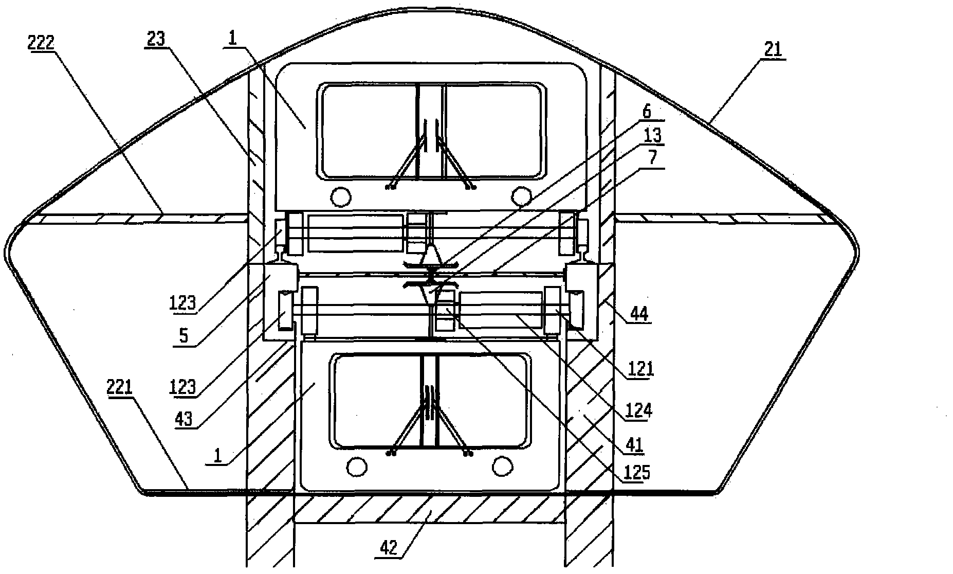
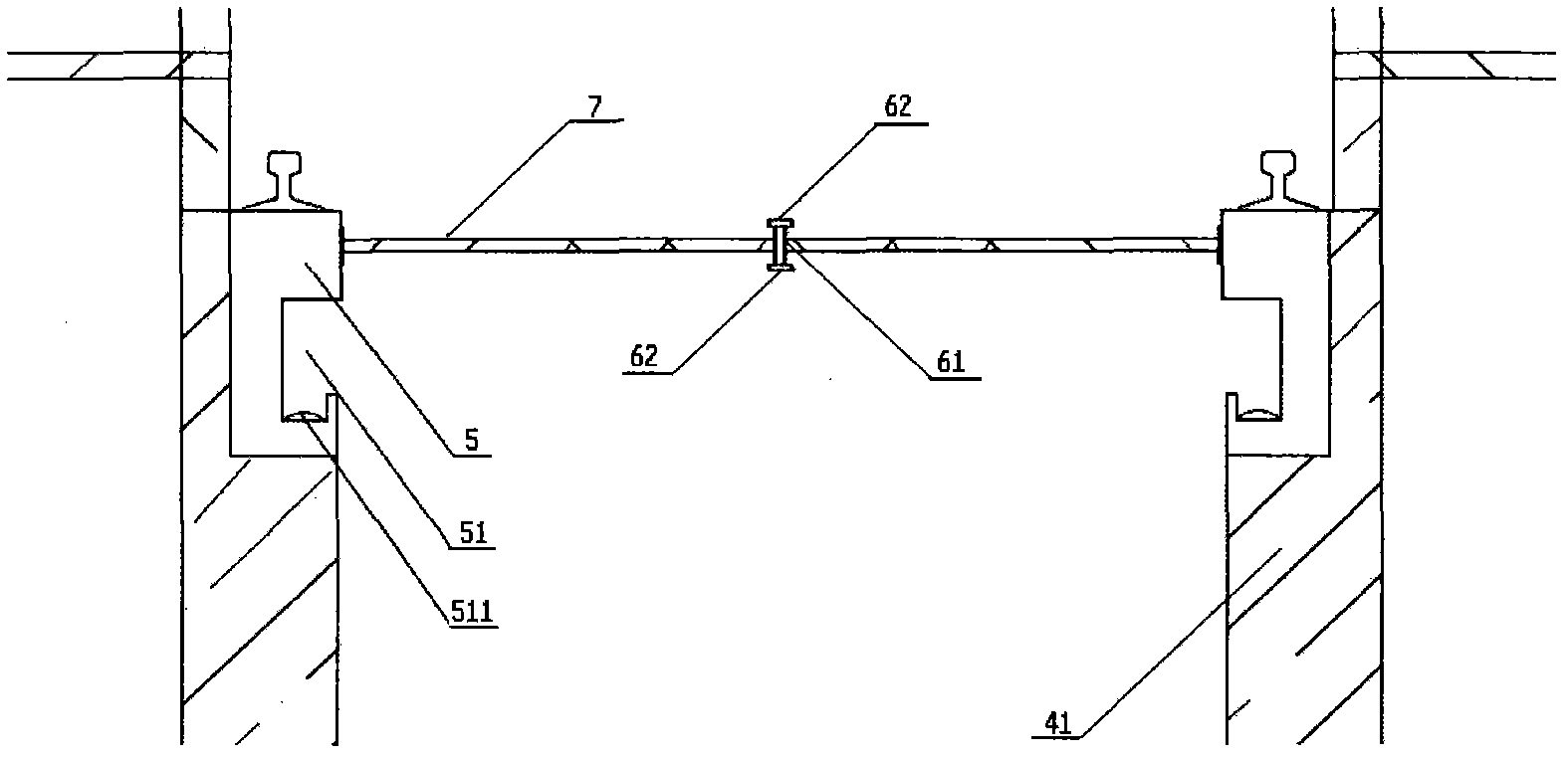
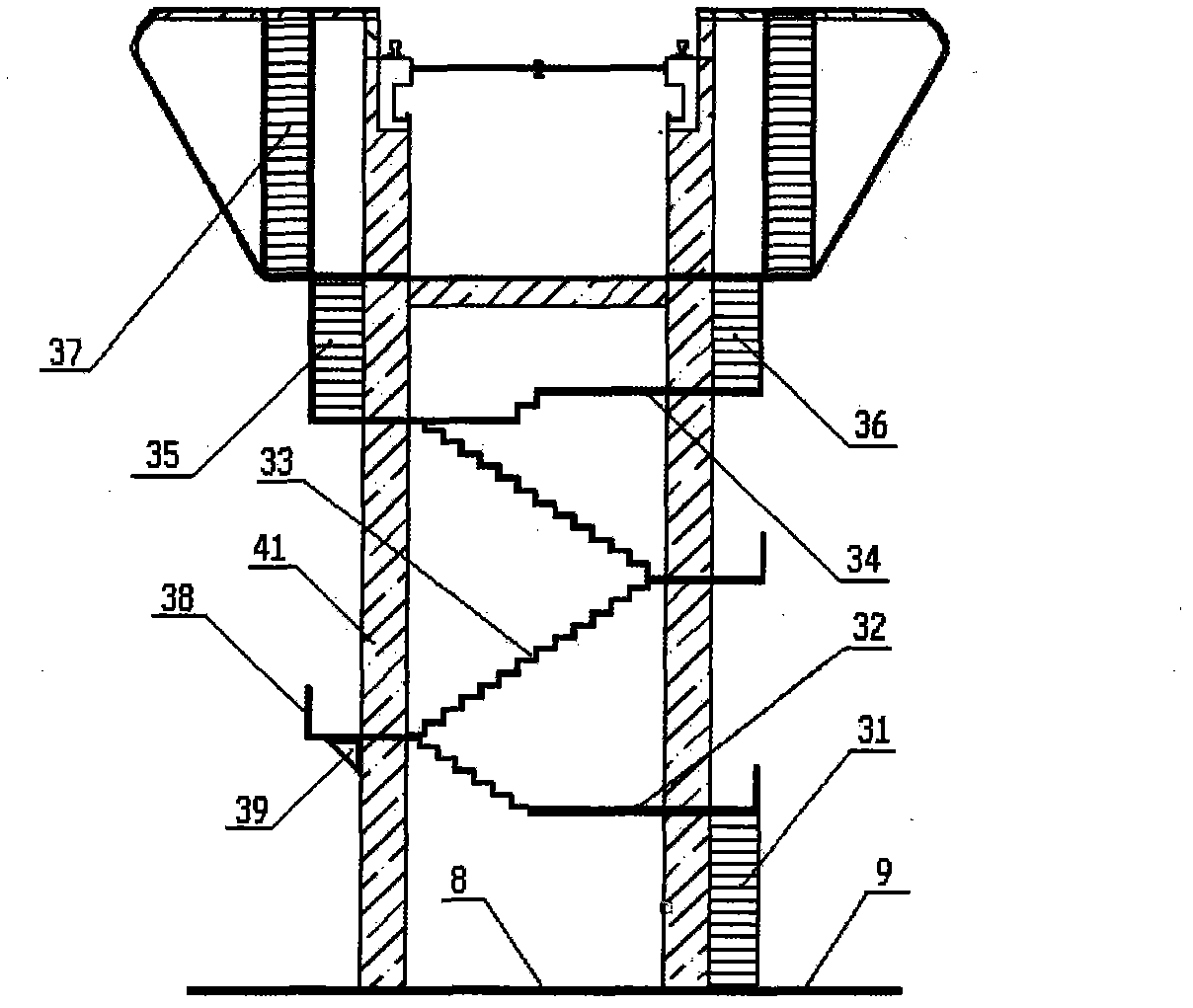
[0035] Such as Figure 1 to Figure 4 As shown, the new urban traffic system with double-deck operation and two-way traffic is mainly composed of vehicles 1, stations 2, stairs 3, bridge piers 4, tracks 5, current receiving rails 6 and connecting plates 7, and bridge piers 4 span the bicycle lane 8 On, the track 5 is erected in the track placement area 43 at the top of the pier 4, and there is a connecting rod 7 between the two tracks to connect the receiving rail 6. The upper train runs along the top of the track, and the lower train runs along the groove 51 below the track. The station 2 is composed of a main frame 21, a pedestrian passage 22, frame pillars 23 and station facilities 24. The main frame 21 is surrounded by a plurality of arc-shaped transverse beams and longitudinal beams and a plurality of glass plates, and the solar panels are located on the glass plates. Below, facilities such as seats are arranged on the pedestrian passage 22, and the pedestrian passage 22 i...


PUM


Abstract

The invention relates to a double-layer running urban rail transportation system, which mainly consists of trains, a station, stairs, bridge piers, rails, connecting plates and a current collection rail, wherein the bridge piers are arranged at both sides of a cycle path, the rails are erected at the top ends of the bridge piers, the trains run along the upper layer and the lower layer of the rails, the upper layer and the lower layer are non-interfering with each other, the double-layer running and the directional passing are realized, a suspension type train runs at the lower layer, train wheels run in grooves under the rails, the station is fixedly arranged on the bridge piers, the two sides of the rails are provided with an upper pedestrian path and a lower pedestrian path, the station is connected with the ground by the stairs, and passengers go up to the pedestrian paths at the two sides through elevators or the stairs around the bridge piers, so as to get on or off the double trains. The transportation method has the advantages that the structure is simple, the manufacturing cost is low, the convenience is provided for the passengers, safety and stability are realized, and meanwhile, the space above the road can be sufficiently utilized.

Description

(1) Technical field [0001] The invention relates to a vehicle, which is an urban rail transit system capable of realizing double-deck operation and two-way traffic. (2) Background technology [0002] The urban land resources are limited, the space is small and congested, and the speed and efficiency of existing vehicles are also limited due to the limitation of road resources and the influence of traffic lights. To deal with the increasing passenger flow, a viaduct design is adopted, but the viaduct piers occupy the road space. Many cities have built new subways and light rails, but the cost of subways and light rails is high, taxis are inefficient in operation, rapid transit occupies road resources, and ordinary buses are slow and cannot adapt to the fast-paced life of the city. These transportation tools and facilities cannot effectively solve congestion. [0003] People have also proposed many solutions to traffic problems, such as rationally adjusting traffic flow accord...

Claims


Application Information

Patent Timeline
IPC IPC(8): B61B13/00B61B15/00B61B1/00B60L5/18
CPCY02T30/00
Inventor 张佳伟
Owner 张佳伟
Learn More