Dropping head apparatus

A technology of water drop head and accommodation part, which is applied in water supply equipment, indoor sanitary pipeline installations, buildings, etc., and can solve problems such as easy loss, sticking foreign objects, and many components

Inactive Publication Date: 2013-07-24
THANK GOD ENTERPRISE
View PDF6 Cites 2 Cited by
  • Summary
  • Abstract
  • Description
  • Claims
  • Application Information

AI Technical Summary

Problems solved by technology

[0003] There are many kinds of common drain head structures. The most basic structure is to screw a cover body with holes (grooves) on the drain hole. It can be blocked on the cover body, but its disadvantage is that the cover body must be unscrewed to clean up, which is extremely inconvenient; therefore, it can also be seen that an improved drain head device is generally installed in the drain hole of the sink of the sink. It includes a movable upper cover, a rubber auxiliary cover, and a filter body with a certain capacity. Usually, a space with an outer diameter slightly larger than the drain pipe is provided at the place where the drain pipe connects to the drain hole, and the filter body can be provided to be placed on it. Then cover the auxiliary cover and the upper cover on the filter body in sequence. The upper cover can completely close the drain hole so that the water in the tank will not be discharged, and the top of the upper cover is equipped with a pull ring. Provide the user to pull the upper cover, so that the water flows through the auxiliary cover and the filter body, and then is discharged into the drain pipe through the filter holes of t

Method used


Image

  • Dropping head apparatus
  • Dropping head apparatus
  • Dropping head apparatus

Examples


Embodiment Construction

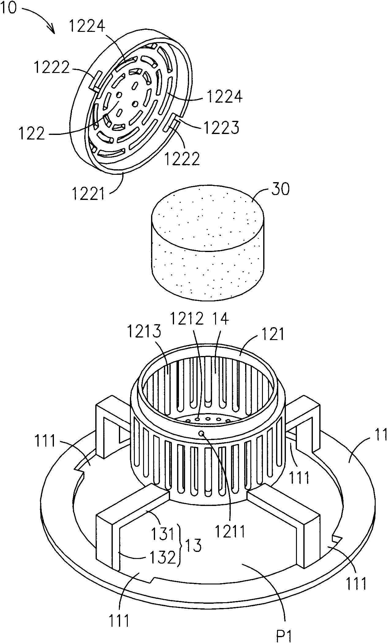
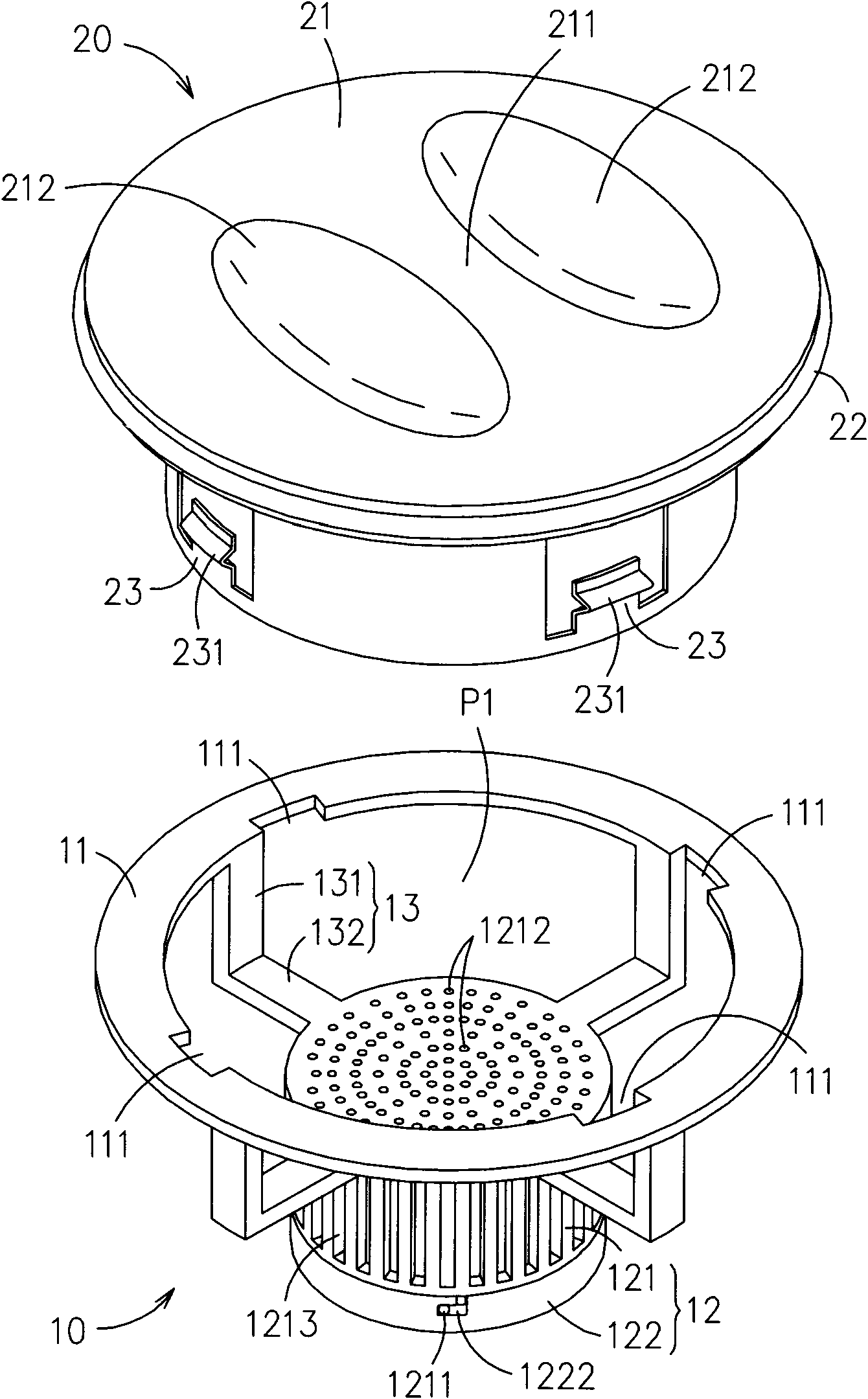
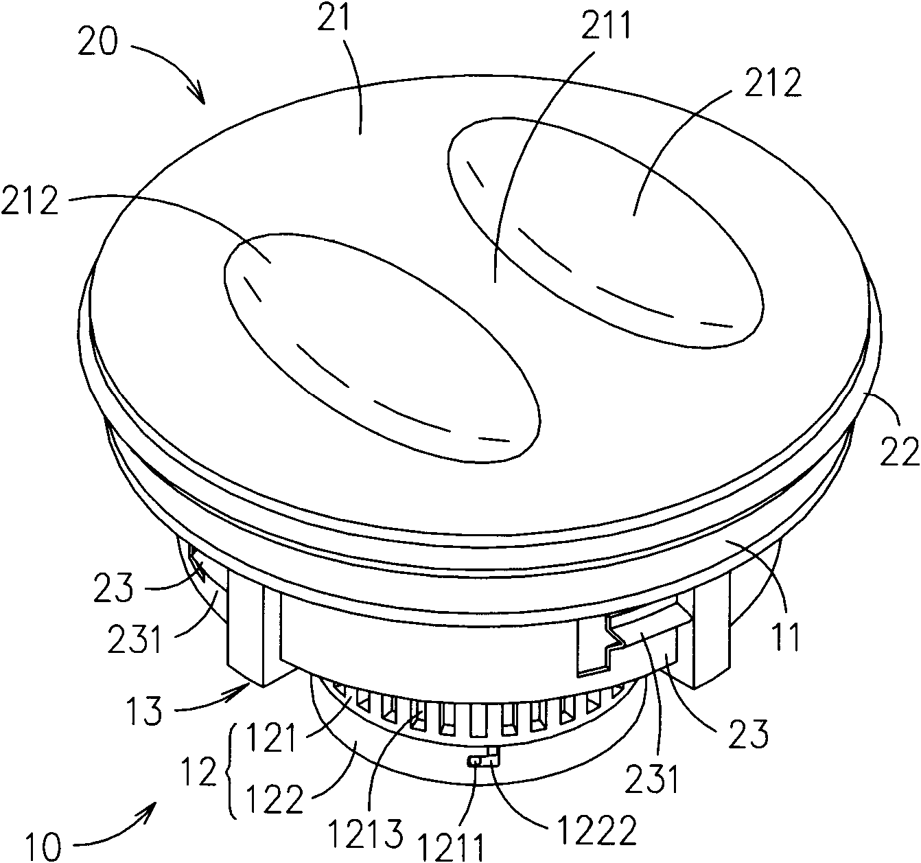
[0021] see Figure 1 to Figure 4 As shown, the drain head device provided by the present invention includes a body 10 and a first cover 20, figure 1 and figure 2 The main body 10 is a structure with opposite sides. The main body 10 is composed of an erecting portion 11 and an accommodating portion 12. A plurality of rod bodies 13 are arranged between the erecting portion 11 and the accommodating portion 12. The plurality of rod bodies 13 are used as The connecting portion between the erecting portion 11 and the accommodating portion 12 connects the erecting portion 11 and the accommodating portion 12 to each other, and a first hollow portion P1 is formed between the erecting portion 11 and the accommodating portion 12 .

[0022] The erecting part 11 is a circular circular body. The accommodating part 12 is composed of a box body 121 and a second cover body 122. The second cover body 122 is detachably arranged on the box body 121. The box body 121 is A circular cylinder, at ...


PUM


Abstract

The invention relates to a dropping head apparatus, which comprises a body and a first cover body, the body is composed of an erection part and an accommodation part, a connection part is provided between the erection part and the accommodation part, at least a groove is provided at the erection part, at least a first hollowed part is provided between the erection part and the accommodation part, at least a second hollowed part is provided at the accommodation part, an accommodation space is provided at the accommodation part, a water inlet end of a drainpipe is provided at the erection part, the accommodation part and the connection part are suspended at the water inlet end; a first cover body has at least a clamping structure, the first cover body is arranged on a first position and a second position of the body, when the first cover body is positioned at the first position, the clamping structure is embedded in the groove and the first cover body is imbedded in the water inlet end, when the first cover body is positioned at the second position, the clamping structure is provided at the erection part and the first cover body is protruded outside the water inlet end.

Description

technical field [0001] The invention relates to a drain head device, especially a device with a simple structure, which can accommodate cleaning agents, keep the drainpipe clean, have the functions of drainage, filtration, sanitation, etc., and can be quickly disassembled and cleaned. Easy to use downspout device. Background technique [0002] Commonly installed on floors, sinks, and bathtubs, in addition to providing drainage, it also has a filtering function to prevent hair, vegetable crumbs and other debris from falling directly into the drain pipe and causing blockage. [0003] There are many kinds of common drain head structures. The most basic structure is to screw a cover body with holes (grooves) on the drain hole. It can be blocked on the cover body, but its disadvantage is that the cover body must be unscrewed to clean up, which is extremely inconvenient; therefore, it can also be seen that an improved drain head device is generally installed in the drain hole of ...

Claims


Application Information

Patent Timeline
IPC IPC(8): E03C1/23E03C1/264E03C1/126
Inventor 李一君
Owner THANK GOD ENTERPRISE
Why Eureka
Try Eureka