
Annular pressure monitoring sealing device for geological drilling

A technology of annular pressure and geological drilling, which is applied in construction and other directions, can solve the problems of inability to pressurize leak plugging, well killing, blowout prevention, monitoring, and inability to perform annular pressure, so as to improve the level of drilling technology and have a long service life , The effect of reducing drilling costs

Inactive Publication Date: 2013-07-24
BEIJING INST OF EXPLORATION ENG
View PDF7 Cites 2 Cited by
  • Summary
  • Abstract
  • Description
  • Claims
  • Application Information

AI Technical Summary

Problems solved by technology

[0004] In order to overcome the technical problems that there is no annular pressure monitoring and sealing device in the current geological drilling, it is impossible to monitor and control the annular pressure, and it is impossible to perform complex operations such as pressurized leakage plugging, well killing, and blowout prevention. Annular pressure monitoring and sealing device, which can not only monitor the change of wellbore annular pressure in real time, but also perform operations such as sealing and maintaining pressure, pressure relief, etc., which can greatly improve the effect and quality of plugging, control water gushing to facilitate well killing operations, and has pressure Monitoring, pressure control, maintaining the stability of the hole wall, etc., so as to improve the level of drilling technology and effectively reduce drilling costs

Method used


Image

  • Annular pressure monitoring sealing device for geological drilling
  • Annular pressure monitoring sealing device for geological drilling
  • Annular pressure monitoring sealing device for geological drilling

Examples


Embodiment Construction

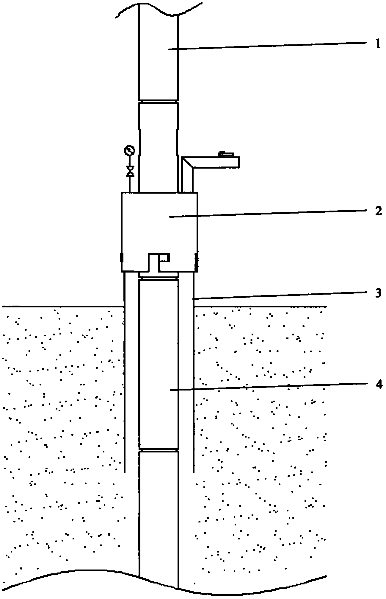
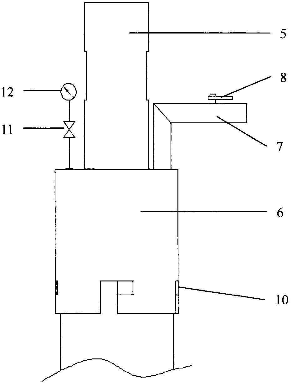
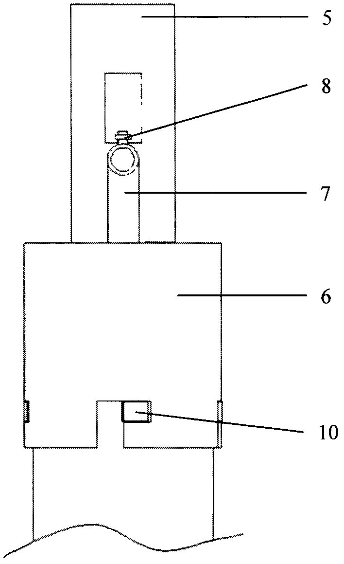
[0016] exist figure 1 Among them, the upper end of the central pipe 5 of the annular pressure monitoring and sealing device 2 is connected to the upper drill pipe 1, and the lower end of the orifice sealing device 2 is connected to the lower drill pipe 4, and is lowered into the designated position in the orifice pipe 3, and the four holes on the orifice pipe 3 A key 10 is screwed into the L-shaped notch of the sealed casing 6 to lock the relative position of the sealed casing 6 and the orifice pipe 3 to complete the installation of the annular pressure monitoring sealing device 2. During work, the annular pressure can be monitored in real time through the pressure gauge 12, and through Changing the opening or closing state of the rotary valve 8 at the upper end of the pressure relief pipe 7 realizes the releasing or maintaining pressure of the annular space.

[0017] exist Figure 5 Among them, the upper and lower ends of the center pipe 5 are processed with trapezoidal thre...


PUM


Abstract

The invention relates to an annular pressure monitoring sealing device for geological drilling, which is applicable to drilling hole maintenance operation such as pressure monitoring, pressure control and pressure leak stopping in geological drilling construction. The device consists of a central pipe, a sealing shell, a pressure gauge, a safety valve, a pressure relief pipe, a spin valve, an orifice pipe, keys and a seal ring, wherein the sealing shell is arranged on the central pipe; four L-shaped notches are formed in the sealing shell; the pressure gauge and the safety valve are arranged on the sealing shell in a connected way; the pressure relief pipe is arranged on the sealing shell; the upper end of the pressure relief pipe is provided with the spin valve; the seal ring is arranged on the orifice pipe; the orifice pipe is arranged in the sealing shell; and four keys are welded on the outer wall of the orifice pipe for locking the relative position of the sealing shell and the orifice pipe. According to the device, the annular pressure change of a shaft can be monitored in real time, and meanwhile, operations such as sealing pressure maintaining and pressure relief can be performed; the device has effects of monitoring and controlling the pressure, keeping a hole wall stable and the like; the leak stopping effect and quality can be greatly improved and water burst is controlled to facilitate kill operation; and thus, the level of the drilling technology is improved and the drilling cost is effectively reduced.

Description

Technical field [0001] The invention relates to an annular pressure monitoring and sealing device for geological drilling, which is suitable for drilling maintenance operations such as pressure monitoring, pressure control, and pressure plugging in geological drilling construction. Background technique [0002] In geological drilling, the holes are usually open. The disadvantages of this open orifice are: 1. It is impossible to monitor the annular pressure in real time, it is impossible to control the annular pressure, and it is impossible to perform complex operations such as pressure plugging and water inrush control; 2. It is not safe and does not have the ability to deal with blowouts, well kicks, etc. Complicated accident capability; 3. It is not environmentally friendly, difficult to recover drilling fluid, and causes great pollution and damage to the natural environment. [0003] In oil well drilling, sealing devices such as blowout preventers or orifice throttling d...

Claims


Application Information

Patent Timeline
IPC IPC(8): E21B47/117
Inventor 陶士先胡继良张德龙王新萍
Owner BEIJING INST OF EXPLORATION ENG
Learn More