Valve control system

A valve control and power device technology, applied in valve details, valve devices, valve operation/release devices, etc., to solve problems such as valve neck damage and heavy weight

Inactive Publication Date: 2013-07-24
李建彪
View PDF9 Cites 2 Cited by
  • Summary
  • Abstract
  • Description
  • Claims
  • Application Information

AI Technical Summary

Problems solved by technology

The disadvantage of the above-mentioned valve control system is that: the power device and the operating device are designed in one piece, and the fixing frame is directly installed on the valve neck of t

Method used


Image

  • Valve control system
  • Valve control system

Examples


Embodiment Construction

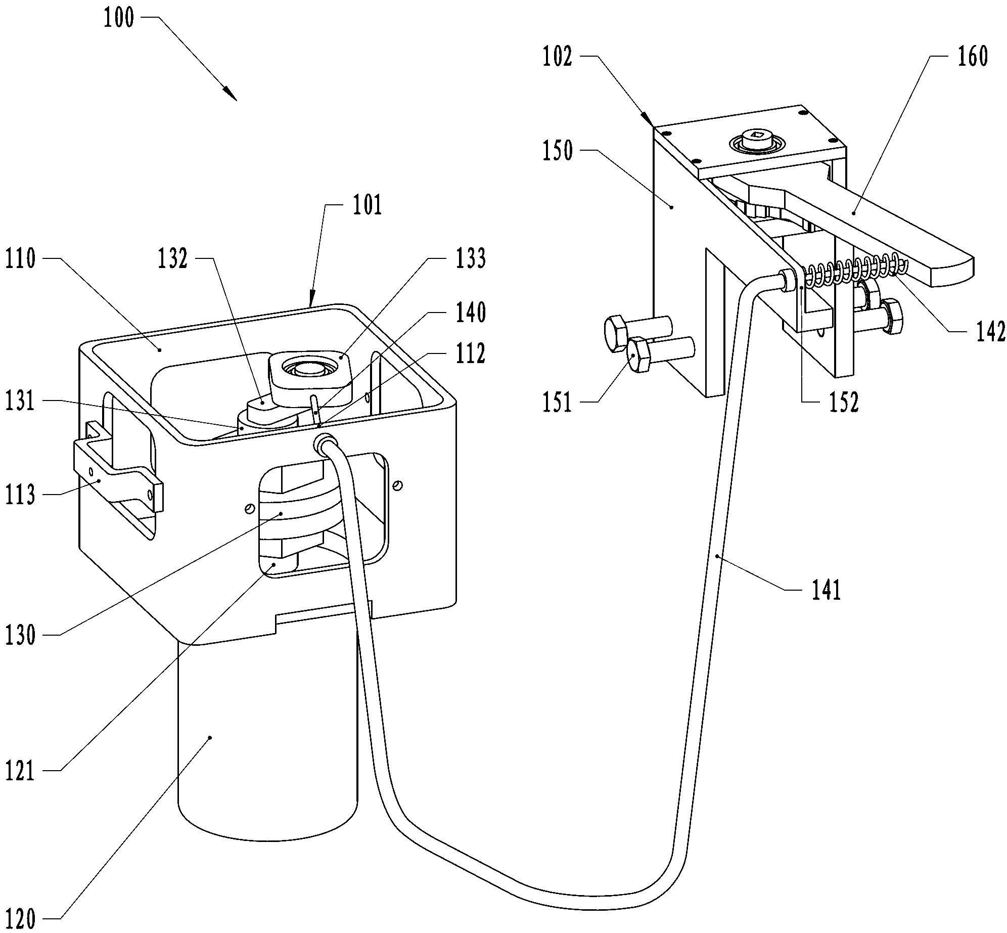
[0020] Such as figure 1 As shown, the valve control system 100 has a power device 101 and an operating device 102 .

[0021] The power unit 101 has a bracket 110, and the deceleration stepping motor 120 is fixed on the bracket 110 by screws. The lower end of the torque limiter 130 is fixed on the rotating shaft 121 of the deceleration stepping motor 120 , and the upper end of the torque limiter 130 is fixed with a reel 131 . One end of the rocker arm 132 is fixed on the reel 131 , and the other end is mounted with a plate 133 that can rotate relative to the rocker arm 132 .

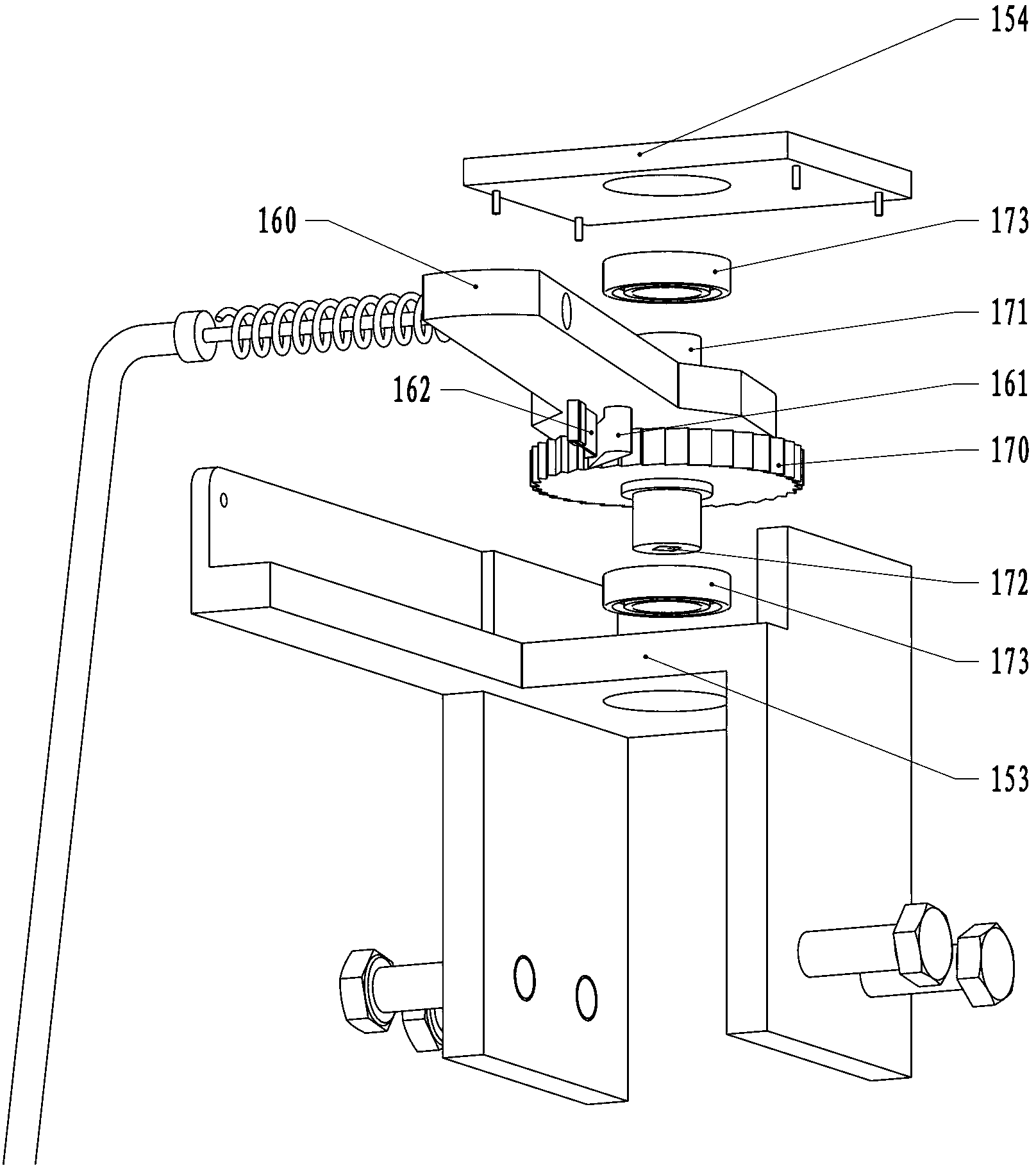
[0022] The operating device 102 has a fixing frame 150 . The fixed frame 150 is installed on the valve neck of the tank body through four bolts 151 arranged at its lower end.

[0023] One end of the flexible cable 140 is fixed on the tail of the rocker 160, and the other end is fixed on the plate 133 as the power output end. The flexible cable sleeve 141 is set on the outside of the flexible cable, an...


PUM


Abstract

The invention relates to a valve control system which comprises a power device and an operating device, wherein the operating device comprises a fixing support, a rocking rod, a ratchet wheel, a pawl, a return spring and a flexible inhaul cable, wherein the rocking rod can be rotationally arranged on the fixing support in a pivoted mode, the ratchet wheel can be rotationally arranged on the fixing support, and is arranged with a same rotary shaft with the rocking rod and used for driving a valve core of a valve, the pawl is arranged on the rocking rod and matched with the ratchet wheel, the return spring is arranged between the fixing support and the rocking rod, one end of the flexible inhaul cable is fixed at the tail of the rocking rod, and the other end of the flexible inhaul cable is fixed at the power output end of the power device. The operating device comprising the rocking rod, the ratchet wheel, the pawl and the fixing support can be installed on the neck portion of the valve, and the power device is far away from the neck portion of the valve and transfers power to the operating device through the flexible inhaul cable. Thus, the power device does not need to be installed on the fixing support, and the mounting weight of the neck portion of the valve is effectively reduced. Even through the valve control system is repeatedly installed for many times, the operating device in small weight can not damage the neck portion of the valve.

Description

technical field [0001] The invention relates to a valve control system, in particular to a valve control system for a tank body containing fluid. Background technique [0002] A tank containing gas or liquid is usually provided with a valve, which is connected to equipment using gas or liquid through a delivery pipeline, and the valve is controlled by a valve control system. The valve control system includes control devices, sensors, power devices and operating devices. Among them, the operating device includes a fixed frame and a connecting piece. The fixed frame is directly installed on the valve neck of the tank body, and the power device is installed on the fixed frame; one end of the connecting piece is connected with the rotating shaft of the power device as the power output end, and the other end is connected with the valve of the valve. The cores are connected. When the sensor installed near the pipeline or the above-mentioned equipment detects gas or liquid leakag...

Claims


Application Information

Patent Timeline
IPC IPC(8): F16K31/44
Inventor 李建彪
Owner 李建彪
Why Eureka
Try Eureka