Form and position tolerance detecting instrument for shaft and sleeve

A form and position tolerance and detector technology, which is applied to instruments, measuring devices, mechanical devices, etc., can solve problems such as inappropriateness, inability to meet workpiece assembly requirements, and affecting the accuracy of form and position tolerance detection.

Active Publication Date: 2013-07-24
河南航天精工制造有限公司
View PDF5 Cites 7 Cited by
  • Summary
  • Abstract
  • Description
  • Claims
  • Application Information

AI Technical Summary

Problems solved by technology

The inspection tool fixes the workpiece by tensioning the tensioning sleeve, which is only suitable for the inspection of cylindrical workpieces with large structures, but it is obviously not suitable for shafts or sleeves with small structures, especially for such types of workpieces. One part of the part is used as a reference segment to detect the coaxiality and other geomet...

Method used


Image

  • Form and position tolerance detecting instrument for shaft and sleeve
  • Form and position tolerance detecting instrument for shaft and sleeve
  • Form and position tolerance detecting instrument for shaft and sleeve

Examples


Embodiment Construction

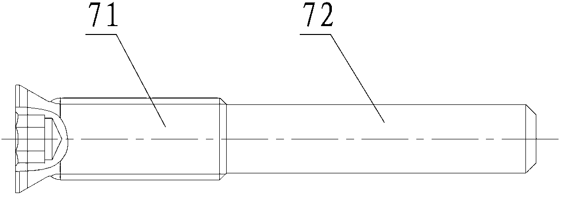
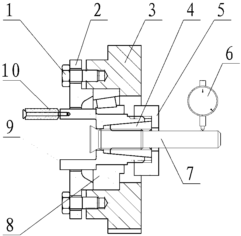
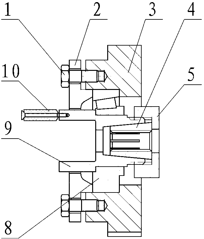
[0016] The embodiment of form and position tolerance detector of the present invention: as Figure 2-4 As shown, it includes a base 3, the base 3 has an inner hole whose axis extends along the left and right directions, a mandrel 9 is inserted in the coaxial gap in the inner hole of the base, and a bearing 8 is installed between the mandrel 9 and the base 3 , so that the mandrel 9 can rotate around its own axis in the base 3 through the bearing 8 . The inner hole of the base has a left-facing limit step surface, the bearing 8 is located in the large hole section on the left side of the limit step surface, and a bearing gland that is press-fitted with the outer ring of the bearing 8 is installed on the left end of the base 3 2. Between the bearing gland 2 and the base 3, there are four adjusting screws 1 uniformly distributed along the inner hole of the base, so that the bearing 8 can be press-fitted between the bearing gland 2 and the limit step surface. The left end of the m...


PUM


Abstract

The invention discloses a form and position tolerance detecting instrument for a part, such as a shaft and a sleeve. The detecting instrument comprises a base and a core shaft which is rotationally arranged in the base through a bearing, wherein a fixing structure used for fixing a reference section of the part to be measured and making the reference section coaxially matched with the core shaft is fixedly arranged on the core shaft; an inner hole of the base is provided with a limit step surface which is leftward and is matched with the bearing in a limit way; the left end of the core shaft extends out of the base, a bearing gland which is matched with the outer ring of the bearing in a compressing way is sleeved on the clearance of the extending part of the core shaft, and adjusting bolts which are peripherally and uniformly distributed along the core shaft are connected between the bearing gland and the base; and an adjusting detection part which is used for detecting the beating degree of the core shaft during a core shaft rotating process through a dial indicator and adjusting the beating degree of the core shaft according to the tightness degree of each adjusting bolt is also arranged on the peripheral surface of the core shaft. While the beating degree of the detected section of the part to be detected in the manner of being relative to the reference section can be detected through the rotation of the core shaft, the influence of the error of the self assembly of the detecting instrument can also be reduced through slight adjustment. The accuracy of detection is improved.

Description

technical field [0001] The invention relates to a detection device for detecting shape and position tolerances of shaft and sleeve parts, in particular to a shape and position tolerance detector. Background technique [0002] For some shaft parts, such as figure 1 The bolts shown generally require certain shape and position tolerance requirements between the threaded section 71 and the polished rod section 72 or between the threaded section 71 and the end surface, such as axiality, verticality, runout, etc., and the threaded section 71 As the reference section of the bolt, the polished rod section 72 serves as the detection section of the bolt. The traditional form and position tolerance detection method adopts the method of projector projection. After the part is placed under the projector to draw the contour line, the coaxiality can be obtained by comparing the contour line in two dimensions, but this kind of detection can only obtain the thread segment The coaxiality be...

Claims


Application Information

Patent Timeline
IPC IPC(8): G01B5/00G01B5/252G01B5/245
Inventor 黄忠宏周杰
Owner 河南航天精工制造有限公司
Why Eureka
Try Eureka