Fluid resistance device

A technology of fluid resistance and components, applied in liquid/fluid solid measurement, detecting fluid flow by measuring pressure difference, pipe components, etc., can solve problems such as difficulty in achieving uniform product performance, inability to achieve compactness, time-consuming and labor-intensive, etc. To achieve uniform performance improvement, compact quantity, simple manufacturing effect

Active Publication Date: 2013-07-24
HORIBA STEC CO LTD
View PDF5 Cites 1 Cited by
  • Summary
  • Abstract
  • Description
  • Claims
  • Application Information

AI Technical Summary

Problems solved by technology

[0006] However, the welding operation is very time-consuming and labor-intensive and requires a certain skill, and there is a problem that the cost increases.
In addition, when the fluid resistance is desired to be increased, the welding operation becomes more difficult if the thin metal tube is made thinner, so there is a problem that the thin metal tube has to be lengthened and compactness cannot be achieved.
In addition, since the capillary member needs to be limited to a certain size, there is also a process of bending the metal capillary tube. Since the inner diameter changes slightly during the bending process, the fluid resistance value changes, so it is difficult to use Uniform performance of each product

Method used


Image

  • Fluid resistance device
  • Fluid resistance device
  • Fluid resistance device

Examples


Embodiment Construction

[0045] Next, the fluid resistance member 100 of this embodiment will be described with reference to the drawings.

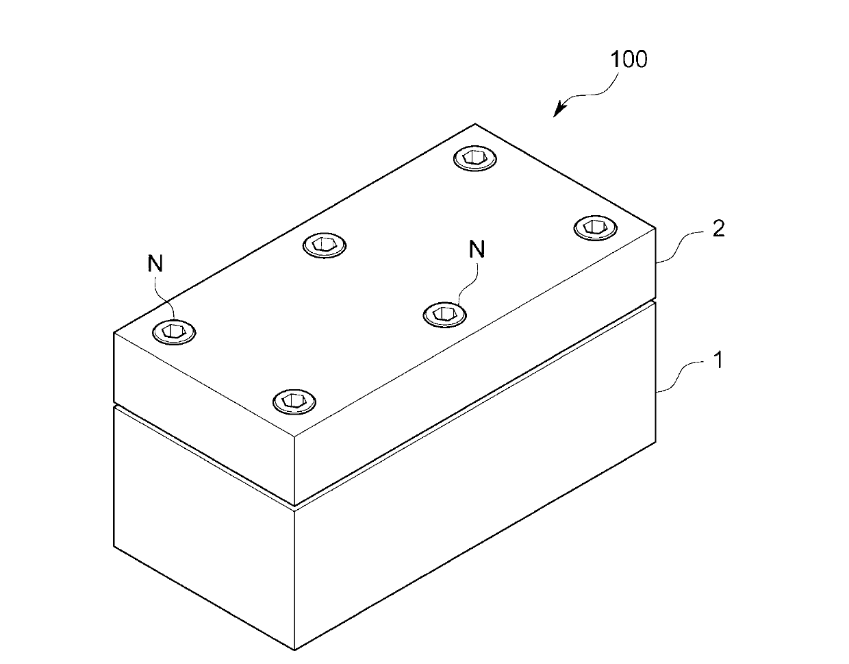
[0046] Such as figure 1 As shown, the fluid resistance component 100 is in the shape of a rectangular parallelepiped as a whole, and constitutes, for example, a part of a flow control device, that is, a part that measures the flow rate by measuring the pressure before and after the fluid resistance component 100 (specifically 3 cc / min or less liquid flow measurement part), in the inside of the fluid resistance component 100, an upstream channel (not shown), a downstream channel (not shown) and a fluid resistance channel 5 for fluid flow are formed, and the fluid resistance The flow channel 5 is connected between the upstream flow channel and the downstream flow channel (refer to figure 2 Wait).

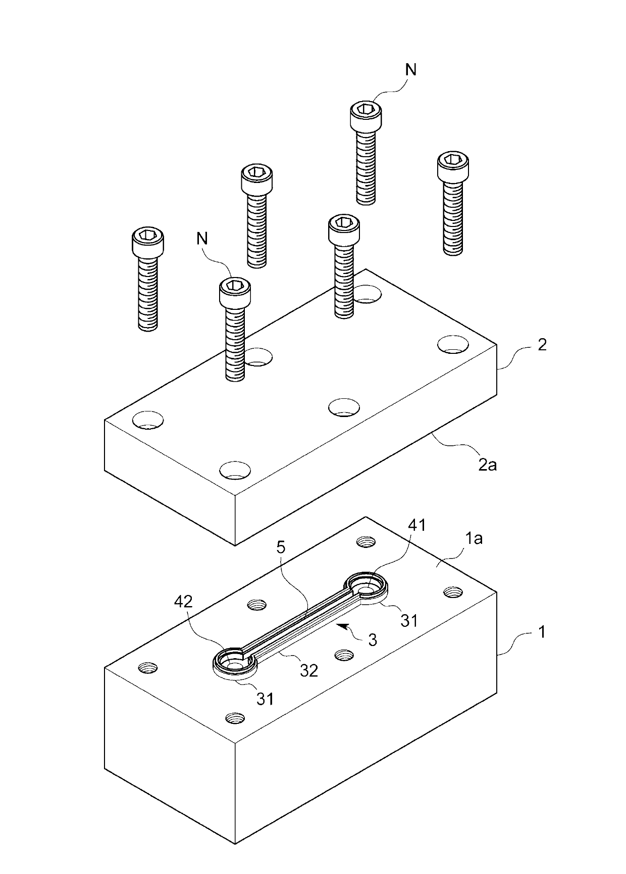
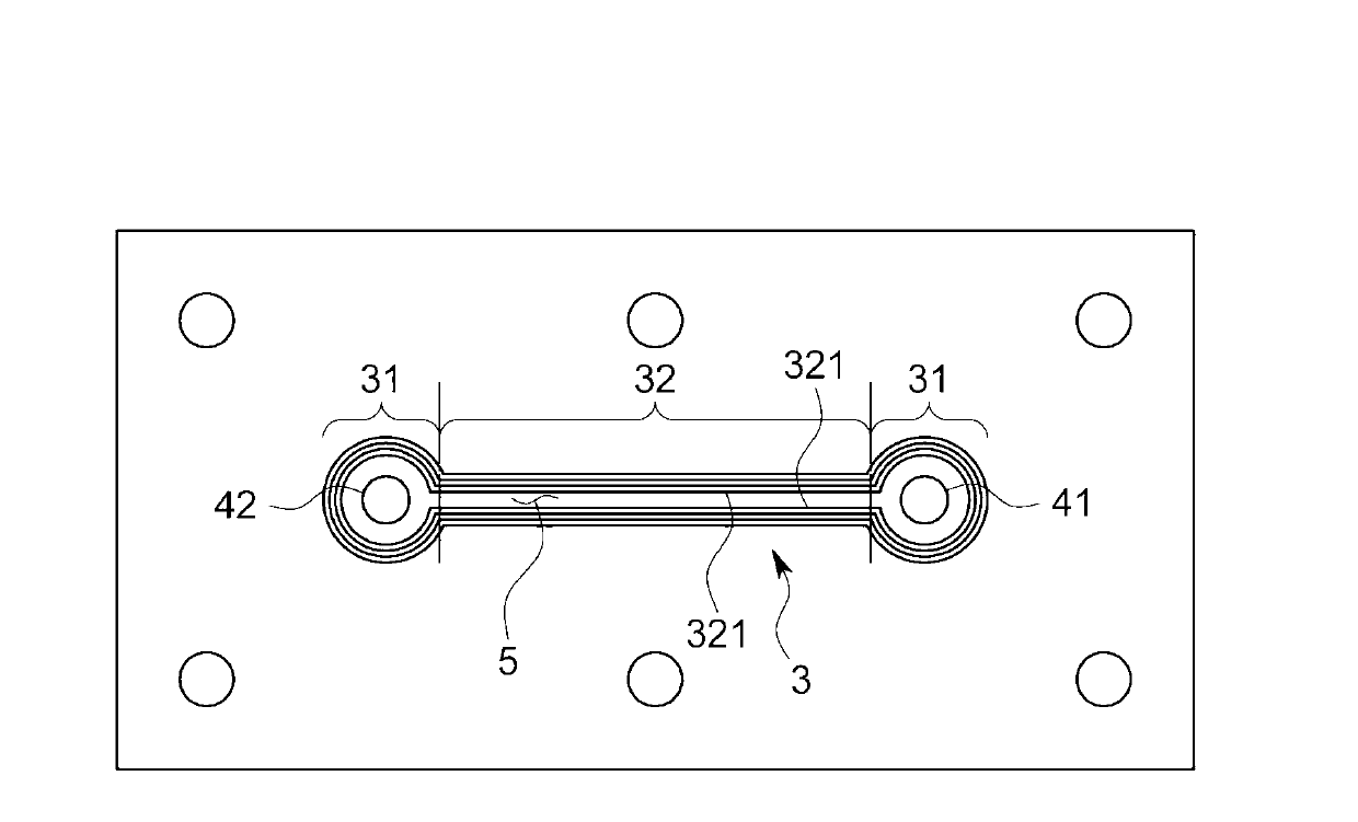
[0047] More specifically, as figure 2 As shown, the fluid resistance member 100 includes a main body member 1 , a cover member 2 , and a ring member 3 , which corre...


PUM


Abstract

In order to provide a fluid resistance device that is easily manufactured, compact, accurate, and uniform in performance, the fluid resistance device comprises two members that have facing surfaces that face each other and a downstream end of the upstream side flow channel and an upstream end of the downstream side flow channel open at positions displaced from each other on the facing surfaces, and a ring body that is arranged to surround the downstream end opening and the upstream end opening and that forms the fluid resistance channel between the downstream end opening and the upstream end opening by being sandwiched by the facing surfaces, and is so configured that the ring body is made of a material harder than that of each member, and the ring body breaks into the facing surfaces by fastening two members so as to make the facing surfaces approach each other.

Description

technical field [0001] The present invention relates to a fluid resistance member used for measuring a flow rate, for example, to generate a pressure difference. Background technique [0002] In a differential pressure flow measuring device, a flow control device, etc., a fluid resistance member for generating a pressure difference is used. Typical fluid resistance members include an orifice member formed by opening fine holes in a plate material, a capillary member formed of a metal thin tube, and the like. [0003] Whether to use an orifice member or a capillary member is appropriately selected according to the flow rate, viscosity, etc. of the fluid. figure 1 , figure 2 etc., conventional capillary components are constructed by welding a metal capillary to a fluid channel formed on a block or the like. [0004] prior art literature [0005] Patent Document 1: Japanese Patent Laid-Open Publication No. 2009-204626 [0006] However, this welding operation is very time-...

Claims


Application Information

Patent Timeline
Patent Type & Authority Applications(China)
IPC IPC(8): G01F1/48
CPCG01F1/74G01F1/34F16L55/027G01F1/48
Inventor 矢田秀贵畑板刚久岸田创太郎
Owner HORIBA STEC CO LTD
Why Eureka
Try Eureka