
Surface mount inductor and method of manufacturing the same

A technology of surface mounting and manufacturing method, applied in the direction of inductor/transformer/magnet manufacturing, transformer/inductor core, transformer/inductor coil/winding/connection, etc., can solve problems such as unfavorable high-density installation, and achieve low height The effect of high-density installation, small electrode area and high-density installation

Inactive Publication Date: 2013-07-24
MURATA MFG CO LTD
View PDF6 Cites 2 Cited by
  • Summary
  • Abstract
  • Description
  • Claims
  • Application Information

AI Technical Summary

Problems solved by technology

Therefore, in order to prevent the external electrodes of adjacent electronic components from contacting each other, such surface mount inductors need to be mounted with a certain distance between the external electrodes of adjacent electronic components. Structure conducive to high-density mounting

Method used


Image

  • Surface mount inductor and method of manufacturing the same
  • Surface mount inductor and method of manufacturing the same
  • Surface mount inductor and method of manufacturing the same

Examples


no. 1 Embodiment

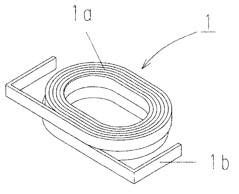
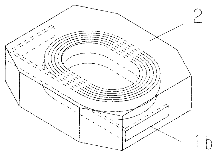
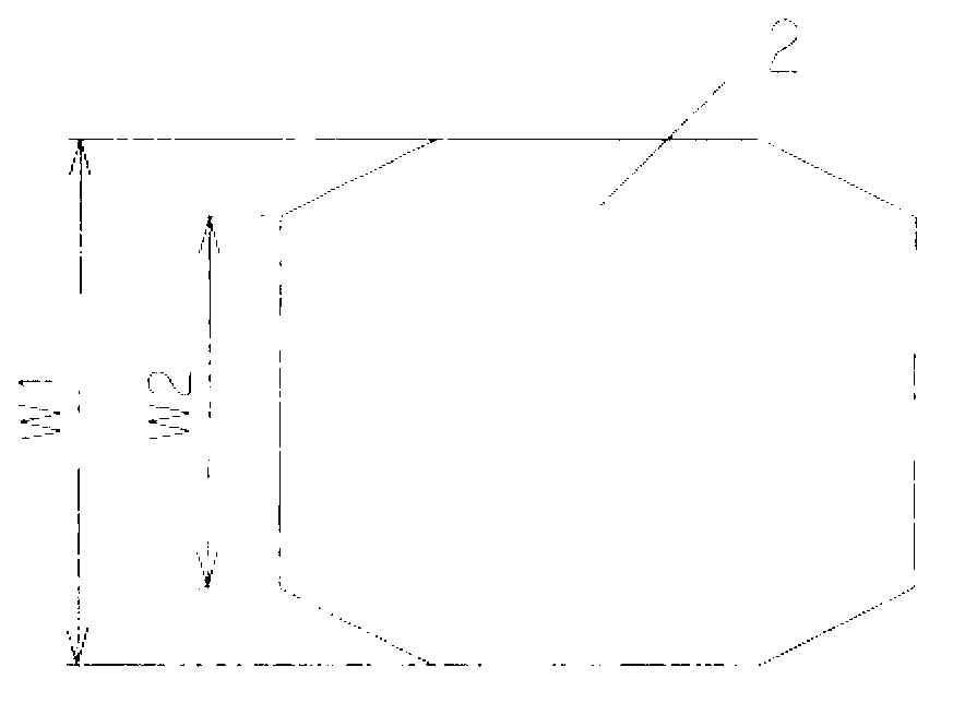
[0026] refer to Figure 1 to Figure 5 , the first embodiment of the surface mount inductor of the present invention will be described. figure 1 A perspective view of a coil used in the following examples is shown. figure 2 with image 3 Represents the core of the first embodiment of the present invention, figure 2 is a stereogram, image 3 For top view. Figure 4 A perspective view showing the surface mount inductor according to the first embodiment of the present invention viewed from the bottom side. Figure 5 A diagram illustrating the external electrodes of the surface mount inductor according to the first embodiment of the present invention is shown.

[0027] First, if figure 1 As shown in , using a winding core with an elliptical cross-sectional shape, a flat wire with a self-adhesive coating is wound into two layers of outer-to-outer winding (wound in such a way that the two wire ends form the outermost circumference). Coil 1. The coil 1 is formed into a sha...

no. 2 Embodiment

[0032] refer to Figure 8 ~ Figure 10 , to describe the second embodiment of the surface mount inductor of the present invention. Figure 8 with Figure 9 Showing the core of the second embodiment of the present invention, Figure 8 is a stereogram, Figure 9 for side view. Figure 10 A perspective view showing a surface mount inductor according to a second embodiment of the present invention viewed from the upper surface side. In addition, the sealing material used in the first embodiment is used in the second embodiment. The description of the part overlapping with the first embodiment is omitted.

[0033] First, the core 12 is formed by compression molding in such a manner that the coil is sealed inside the core 12 with a sealing material. exposed. In this embodiment, as in the first embodiment, the core portion 12 is formed in an octagonal shape, and, as Figure 9 As shown, the upper surface of the core 12 is tapered such that the height H2 of the end surface of th...


PUM


Abstract

The invention aims to provide a miniature surface mount inductor beneficial for being installed onto a circuit board in high density, and a method of manufacturing the surface mount inductor. The surface mount inductor of the invention is characterized by comprising a coil which is formed by winding a wire; a core part which internally seals the core and is mainly composed of magnetic powder and resin; and an external electrode which is letter L-shaped and is formed on the surface of the core part by using conductive paste. The core part is formed to be a shape having an upper surface, a bottom surface, and a pair of opposite end surfaces. The width of each of the pair of the end surfaces is smaller than the width of the central portion of the core part. For the time being, the core part is formed in a mode that the end portions of the coil are respectively exposed from the surfaces of the opposite end surfaces. A printing mode is employed to coat the conductive paste onto a part of the bottom surface and the end surfaces. The external electrode is formed in a manner of being electrically connected with the end portions of the coil. The width of the external electrode is smaller than the width of the central portion of the core part, and the external electrode does not reach the upper surface of the core part.

Description

technical field [0001] The present invention relates to small surface mount inductors and methods of manufacturing the same. Background technique [0002] Surface mount inductors in which a coil obtained by winding a wire is enclosed in a core (core) are widely used. In recent years, along with the miniaturization and thinning of electronic equipment such as mobile phones, miniaturization and reduction in height of electronic components such as surface mount inductors are also required. The applicant proposed a small-sized surface mount inductor using a preformed sheet member and winding the flat wire into a A coil obtained in a spiral shape (Japanese Patent Laid-Open No. 2010-245473). [0003] This surface mount inductor is placed in a molding die in a state where a coil obtained by winding a flat lead wire is placed on a sheet member, and compression-molded at a temperature above the softening temperature of the sheet member to obtain a rectangular parallelepiped molded ...

Claims


Application Information

Patent Timeline
Patent Type & Authority Applications(China)
IPC IPC(8): H01F17/04H01F27/24H01F27/30H01F27/29
CPCH01F3/08H01F27/24H01F27/288H01F27/292H01F41/02
Inventor 狮子仓洋户塚昌明佐佐森邦夫
Owner MURATA MFG CO LTD
Learn More