Eureka AIR delivers breakthrough ideas for toughest innovation challenges, trusted by R&D personnel around the world.

Control circuit and control method of primary side feedback constant current

A control circuit, primary side technology, applied in the direction of electric lamp circuit layout, control/regulation system, electric light source, etc., to achieve the effect of improving the constant current effect

Active Publication Date: 2013-07-24
MAXIC TECHNOLOGY CORPORATION
View PDF5 Cites 32 Cited by
  • Summary
  • Abstract
  • Description
  • Claims
  • Application Information

AI Technical Summary

Problems solved by technology

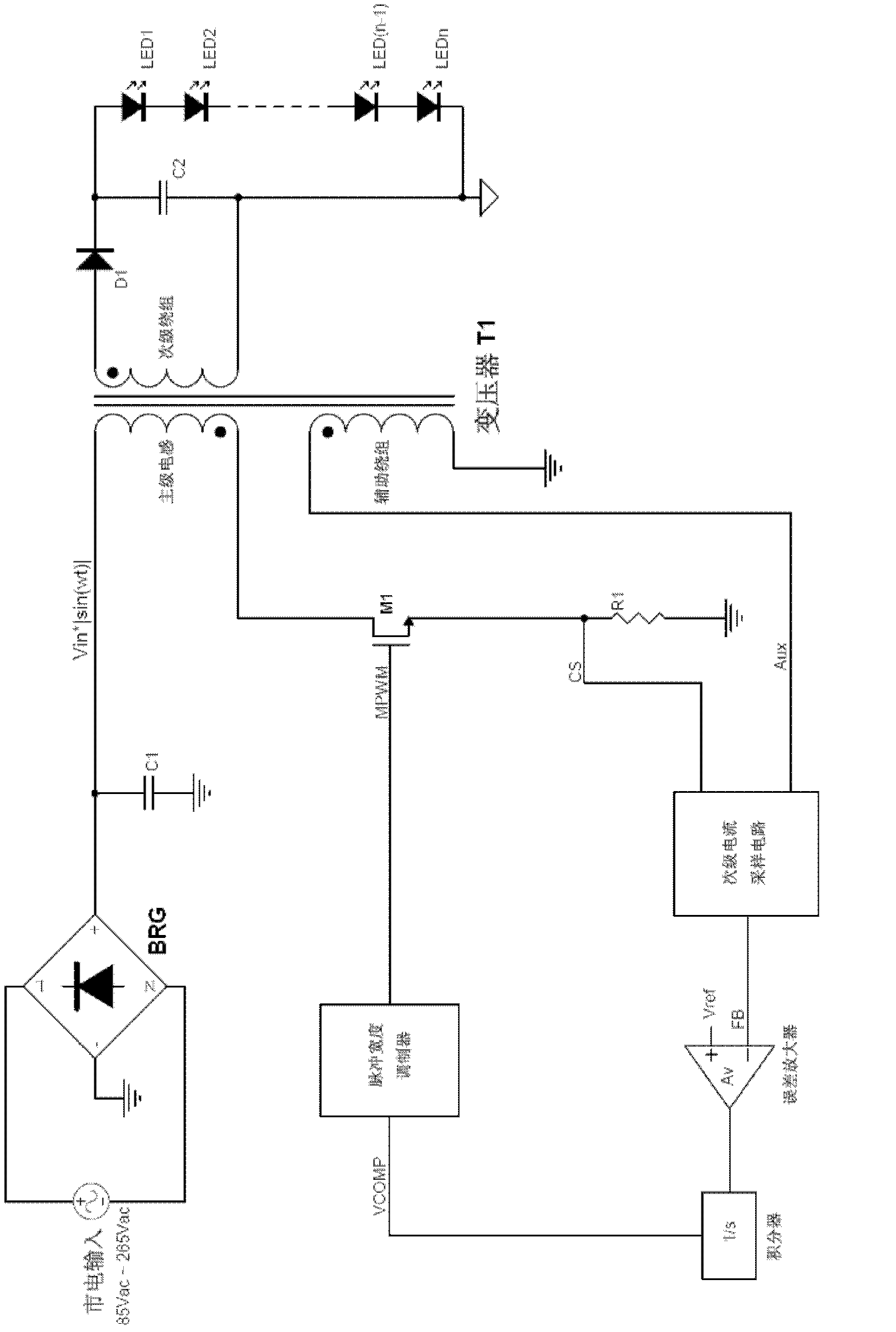
[0004]In this technology, the driving voltage MPWM controlled by the control chip controls the voltage of other nodes, thereby controlling the output current and making it stable. The control chip basically realizes the primary side constant current control and high power factor requirements, but the current chip can only basically meet the primary side constant current control and high power factor requirements, its actual effect is relatively poor, and it does not really realize constant current Function

Method used


Image

  • Control circuit and control method of primary side feedback constant current
  • Control circuit and control method of primary side feedback constant current
  • Control circuit and control method of primary side feedback constant current

Examples


Embodiment Construction

[0019] The specific implementation manners of the present invention will be described in detail below in conjunction with the accompanying drawings of the present invention.

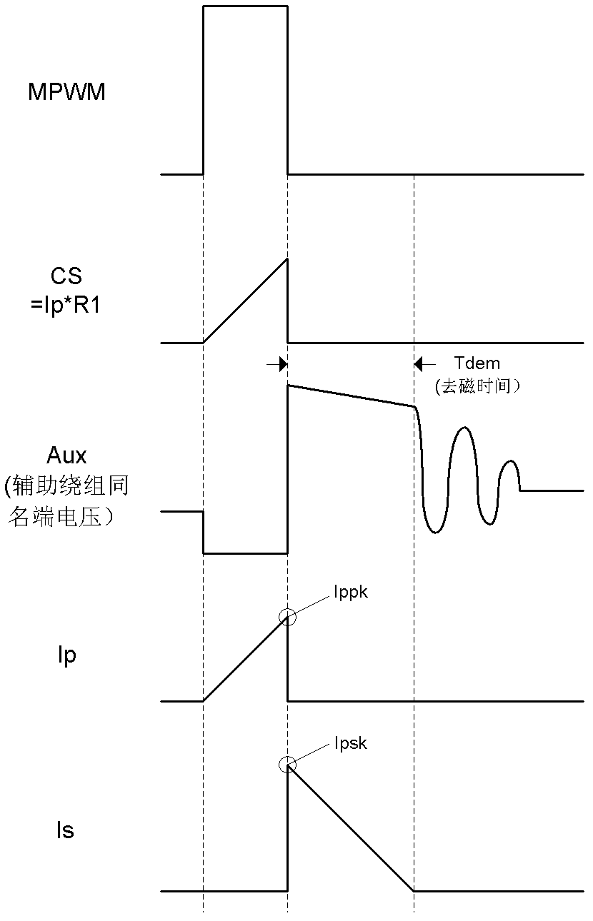
[0020] figure 2 based on figure 1 Waveform diagram of each node under the control of the structure. figure 2 Among them, CS is the voltage waveform at both ends of the sampling resistor R1; Aux is the voltage waveform at the terminal with the same name of the auxiliary winding. According to the working principle of the transformer, the secondary winding voltage is proportional to the auxiliary winding voltage; Ip is the primary inductor current waveform, and Ippk is at In each switching cycle, the peak value of the primary inductor current; Is is the waveform of the secondary inductor current, and Ispk is the peak value of the secondary inductor current in each switching cycle.

[0021] Assuming that the switching period of MPWM is T, then in any switching period nT, the output current of the second...


PUM


Abstract

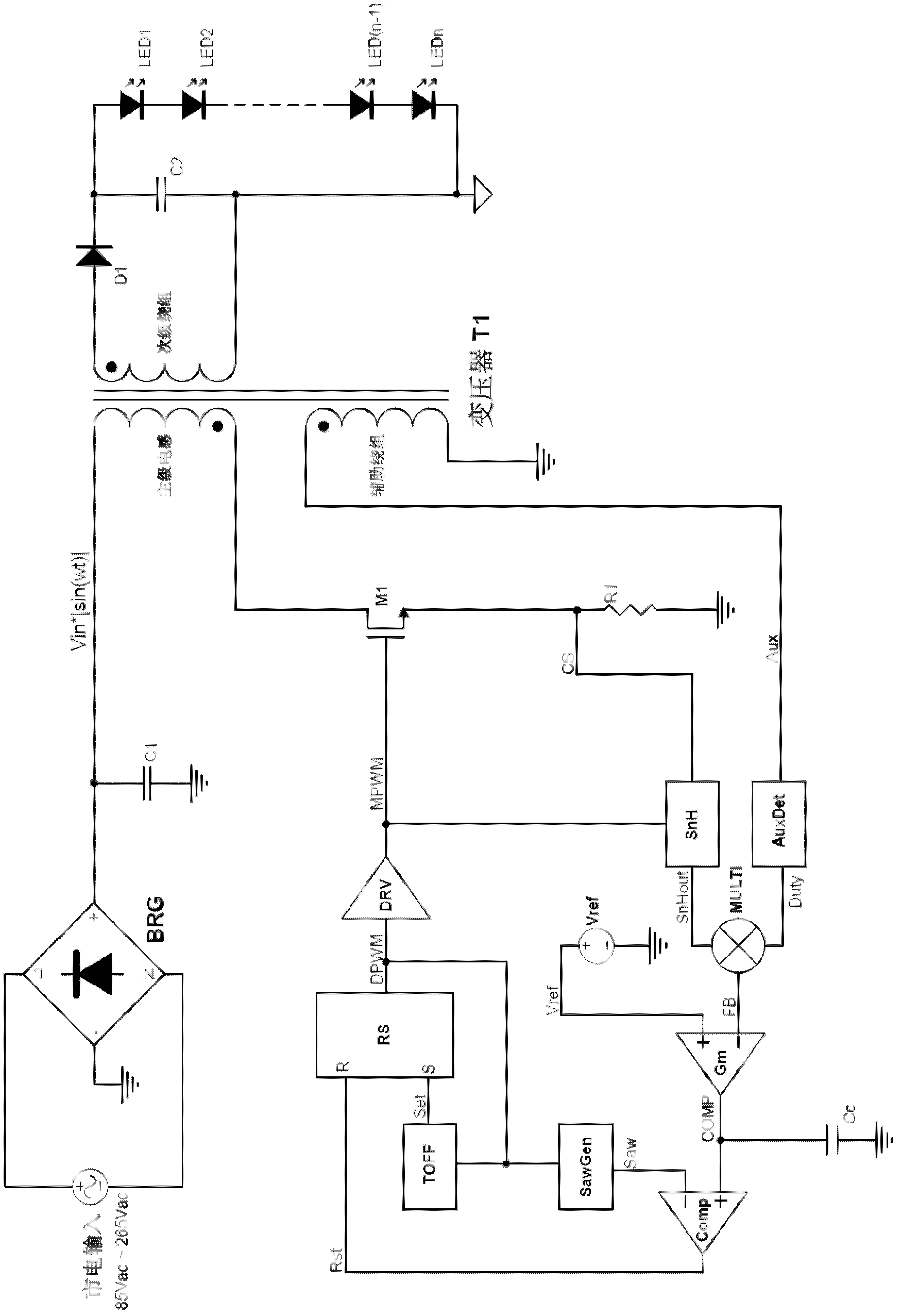
The invention discloses a control circuit and a control method of a primary side feedback constant current of a constant current actuator of an alternating current-direct current (AC-DC) light-emitting diode (LED). The control circuit comprises a power switch tube, a secondary current sampling circuit, an error amplifier, an integrator and a pulse width modulator, wherein the power switch tube controls the work of primary inductance in a discontinuous working mode, the secondary current sampling circuit takes samples of demagnetizing time of a secondary winding and the current peak value of the primary inductance through a primary side auxiliary winding and generates feedback signals corresponding to the average value of a secondary current in each switching period based on the demagnetizing time and the current peak value, the error amplifier amplifies the errors between reference voltage and the feedback signals of a sampling circuit of the secondary current, the integrator carries out integration on the value amplified by the error amplifier, and the pulse width modulator generates pulse width modulation signals to control the power switch tube to work based on the signals output by the integrator. The control circuit and the control method of the primary side feedback constant current improve a constant current effect of output currents, and achieves high-precision constant current control with high power factor control.

Description

technical field [0001] The invention belongs to the technical field of LED constant current drivers in AC-DC converters, and relates to a primary side feedback constant current control circuit with high power factor in a flyback converter and a control method thereof. Background technique [0002] At present, LED drivers usually need to meet the following requirements: output constant current, high power factor and electrical isolation. Among them, the output constant current is determined by the characteristics of the LED itself, the high power factor is to reduce the pollution of the driver to the public grid, and the electrical isolation is for safety considerations. Constant current is also a steady current, and the constant current system is a circuit system that stabilizes the output current or the output average current. The function of the constant current system is to stabilize the output current, no matter how the input voltage and output load change, the output ...

Claims


Application Information

Patent Timeline
Patent Type & Authority Applications(China)
IPC IPC(8): H02M3/335H02M1/42H05B37/02
CPCY02B70/126Y02B70/10
Inventor 郭越勇
Owner MAXIC TECHNOLOGY CORPORATION
Why Eureka
Eureka Blog
Learn More