Programmable gain isolation amplifier circuit and implement method thereof

A technique of isolating amplifier circuits and programming gain, applied in the direction of gain control, amplification control, electrical components, etc., can solve the problems of large size and power consumption, inability to use, and inability to change continuously, so as to improve amplification accuracy and eliminate zero drift Effect

Active Publication Date: 2013-07-24
ANSTEEL GRP MINING CO LTD
View PDF6 Cites 1 Cited by
  • Summary
  • Abstract
  • Description
  • Claims
  • Application Information

AI Technical Summary

Problems solved by technology

[0005] 1) Micro relays are used for signal isolation, and the isolation effect is acceptable, but the speed is slow, the volume and power consumption are large, and the service life is low;
[0006] 2) Using linear photocoupler isolation, its circuit is simple, the effect of this isolation is not bad, but the disadvantage is that the linearity is poor when the signal is small, and it cannot be used in occasions with high precision requirements;
[0007] 3) Using magnetic or transformer isolation, this isolation effect is good, but the technology is complicated, expensive, large in size and power consumption, and some signals cannot be directly used, such as DC signals;
[0008] 4) Galvanic isolation is used between the input circuit and the output circuit, the technology is complicated, and it cannot be used in some occasions;
[0010] 1) The feedback resistor network of the amplifying circuit is controlled by a micro switch, which can change the gain of the amplifying circuit, but it cannot be automated;
[0011] 2) The feedback resistor network of the amplifying circuit is controlled by an electronic switch, which can change the gain of the amplifying circuit, but the resistance value in the feedback resistor network is fixed and cannot be changed continuously, that is, the gain of the amplifying circuit cannot be continuously changed;
But the resistance that determines the magnification is still fixed, so the gain of the amplifying circuit cannot be continuously variable

Method used


Image

  • Programmable gain isolation amplifier circuit and implement method thereof
  • Programmable gain isolation amplifier circuit and implement method thereof
  • Programmable gain isolation amplifier circuit and implement method thereof

Examples


Embodiment 1

[0035] Embodiment 1: The signal sent by the signal conversion unit is a non-thermal resistance signal.

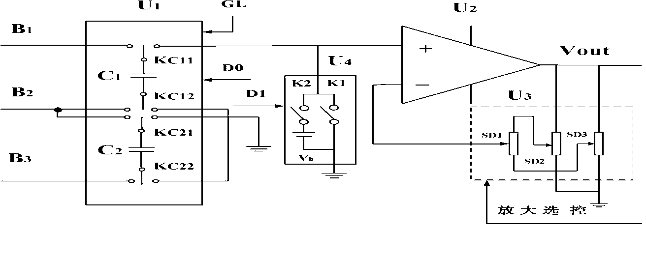
[0036] Such as figure 2 shown, the isolation unit U 1 Including input terminals B1, B2 and B3, conversion capacitors C1 and C2, microelectronic digital switch groups KC11, KC12, KC21 and KC22, gating signal GL, control signal D0 of microelectronic digital switch, when the isolation unit U1 receives the signal conversion When the signal sent by the unit is a non-thermal resistance signal, it is connected by the input terminals B1 and B2 of the isolation unit U1, and there is no signal input at the terminals B2 and B3 at this time. At this time, the embedded microcomputer sends a low-level signal to the control signal D0 of the microelectronic digital switch, so that KC11, KC12, KC21, and KC22 are all on the left side. At this time, the conversion capacitors C1 and C2 are in the state of receiving signals. When the control signal D0 of the microelectronic digital switch is...

Embodiment 2

[0041] Embodiment 2: The signal sent by the signal conversion unit is a thermal resistance signal.

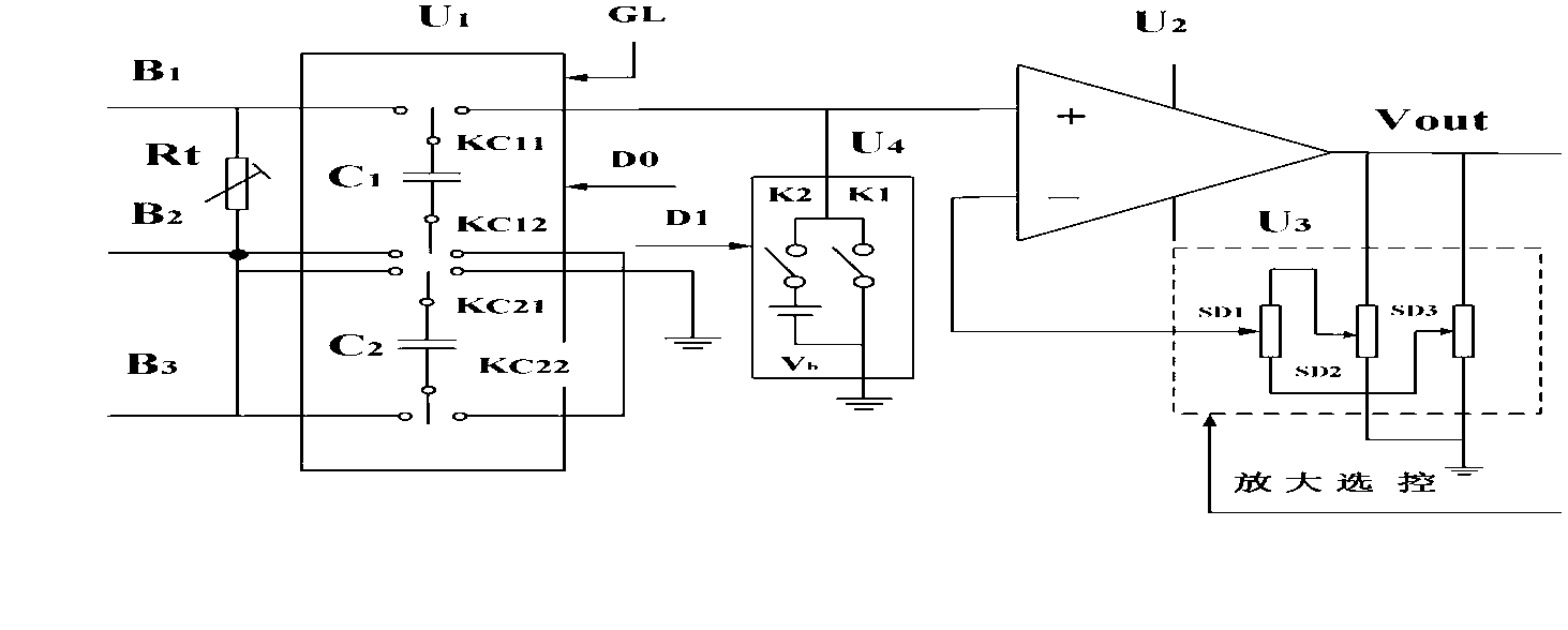
[0042] Such as image 3 As shown, when the isolation unit U1 receives the signal sent by the signal conversion unit as a thermal resistance signal, the input terminals B1 and B2 are connected to the thermal resistance Rt, and the terminals B2 and B3 are connected to the lead wire of the thermal resistance Rt, because the thermal resistance is used to measure When the temperature is high, the voltage drop on the wire should be deducted. The working process when measuring temperature with thermal resistance is: make the microelectronic digital switch group KC11, KC12, KC21, KC22 all close to the left, and the conversion capacitor C1 receives the voltage Vc1 on the thermal resistance Rt (上+,下-) , conversion capacitor C2 receives thermal resistor Rt lead voltage V 引线(上+,下-) , when the microelectronic digital switch groups KC11, KC12, KC21, KC22 are all on the right side, the uppe...


PUM


Abstract

The invention belongs to the technical field of isolation amplifier circuits, and particularly relates to a programmable gain isolation amplifier circuit and an implement method thereof. The programmable gain isolation amplifier circuit comprises an isolation unit U1 and a programmable gain amplifier circuit, wherein the isolation unit U1 comprises an input end, a conversion capacitor, a micro-electronic digital single-pole double-throw switch, gating signals, and control signals of the micro-electronic digital switch, and the programmable gain amplifier circuit comprises a precise integrated operational amplifier, a programmable resistor network and a gain measuring circuit. The programmable resistor network is composed of digital potentiometers, and the gain measuring circuit comprises a digital switch, standard voltage and the control signals of the digital switch. The programmable gain isolation amplifier circuit can achieve complete isolation between a signal end and the amplifier, can overcome the zero-shift phenomenon of the amplifier circuit, is strong in continuity of gain selection, and can remarkably improve amplification precision.

Description

technical field [0001] The invention belongs to the technical field of isolation amplifying circuits, in particular to a programmable gain isolation amplifying circuit and a realization method thereof. Background technique [0002] In reality, there is a lot of information that needs to be collected and turned into usable information. Basic information is transformed from signals. There are two types of signals in nature, one is analog signals, which are continuous or slowly changing signals over time; the other is signals that change intermittently over time, called digital signals, which can be used for digital processing , or to the computer for processing. However, in reality, a large amount is an analog signal, which is extracted by various sensors. [0003] Analog signals generally vary in size, and some of them are tiny signals that need to be amplified for further use. In the amplification process, in order to improve the transmission accuracy, the signal should ...

Claims


Application Information

Patent Timeline
Patent Type & Authority Applications(China)
IPC IPC(8): H03G3/20
Inventor 王欢徐鑫鲁鹏云门涛王勇娄全发王春岩
Owner ANSTEEL GRP MINING CO LTD
Why Eureka
Try Eureka