Feeding robot of drilling and tapping machine tool

A technology of robots and machine tools, applied in the field of transmission shafts, can solve the problems of high labor intensity, low production efficiency, and short service life of workers, and achieve the effects of improving production efficiency and economic benefits, saving processing time, and reasonable and practical design

Inactive Publication Date: 2013-07-31
DONGYING XINSHENG MACHINERY
View PDF7 Cites 3 Cited by
  • Summary
  • Abstract
  • Description
  • Claims
  • Application Information

AI Technical Summary

Problems solved by technology

There are disadvantages such as bulkiness, poor quality, short service life, high energy consumption of equipment, low production efficiency, high labor intensity of workers, low product quality stability, and prone to failure.

Method used


Image

  • Feeding robot of drilling and tapping machine tool

Examples


Embodiment Construction

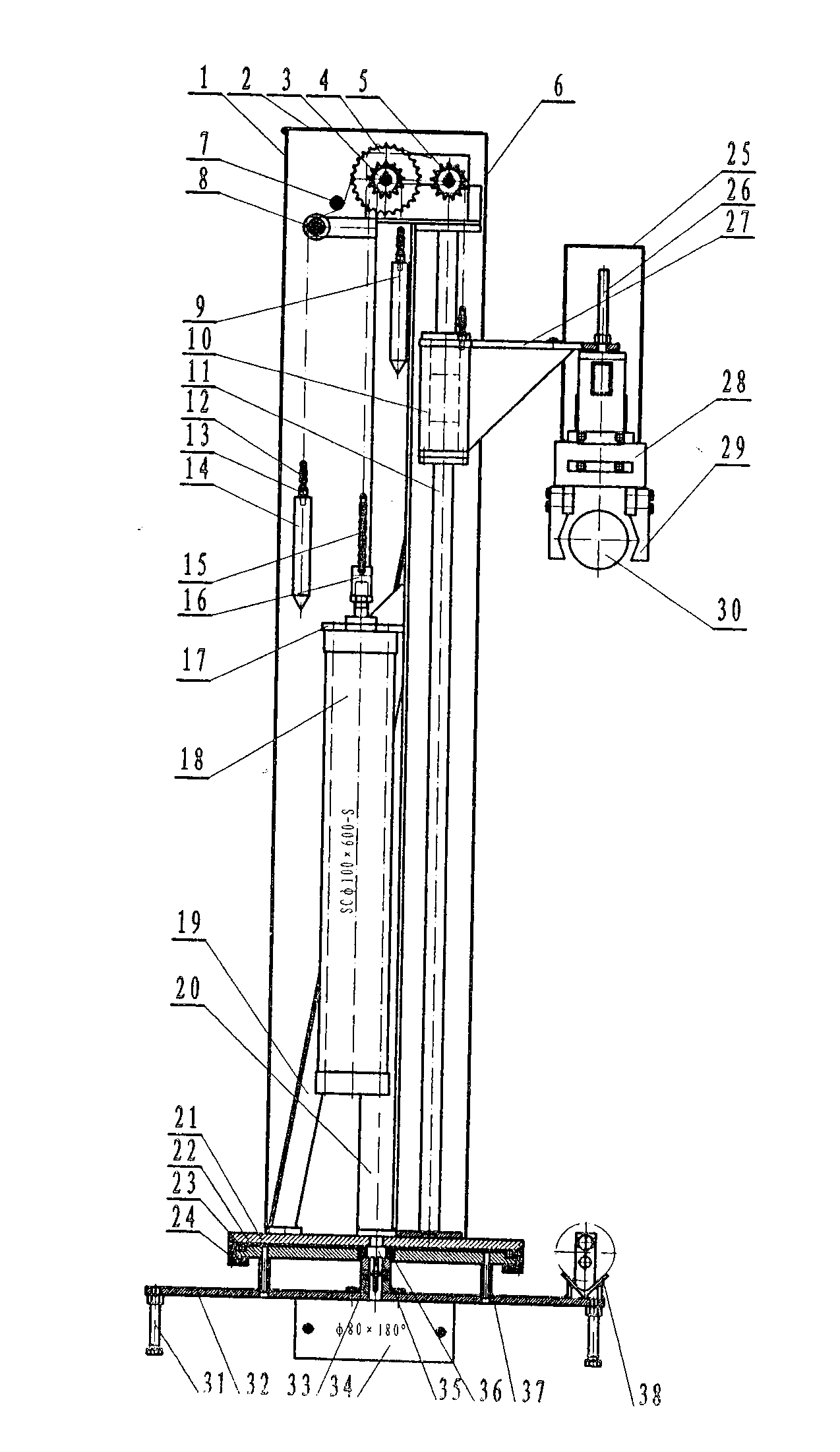
[0006] As shown in the figure, the feeding robot for drilling and tapping machine tools is mainly composed of a cover body 1, a cover cover 2, a small driving sprocket 3, a large driving sprocket 4, a supporting sprocket 5, a dust shield 6, and a chain pressing wheel 7. Support wheel 8, first weight 9, sliding sleeve 10, polished rod 11, lifting chain 12, chain joint 13, second weight 14, driving chain 15, cylinder joint 16, cylinder fixing plate 17, lifting cylinder 18. Column tie bars 19, column angle iron 20, turntable 21, load-bearing plate 22, turntable steel ball 23, turntable pressure plate 24, manipulator cover 25, lifting screw 26, lifting arm 27, manipulator cylinder 28, manipulator claw 29, workpiece 30 , supporting foot 31, bottom plate 32, coupling 33, gyrator cylinder 34, turntable shaft 35, turntable bearing 36, bottom plate spacing sleeve 37 and discharge V-shaped iron 38; 2 and dust baffle 6, the position on the inside is provided with driving small sprocket 3...


PUM


Abstract

A feeding robot of a drilling and tapping machine tool mainly comprises a housing body (1), a housing upper cover (2), a small driving chain wheel (3), a big driving chain wheel (4), a bearing chain wheel (5), a dust baffling plate (6), a chain pressing wheel (7), a bearing wheel (8), a first hammer (9), a sliding sleeve (10), a polished rod (11), a hoisting chain (12), a chain connector (13), a second hammer (14), a driving chain (15), a cylinder connector (16), a cylinder fixing plate (17), a hoisting cylinder (18), an upright post lacing bar (19), upright post angle iron (20), a turnplate (21), a bearing plate (22), turnplate steel balls (23), a turnplate pressing plate (24), a manipulator housing (25), a hoisting screw rod (26), a hoisting arm (27), a manipulator cylinder (28), a manipulator claw (29), a workpiece (30), bearing feet (31), a bottom plate (32), a shaft coupler (33), a rotatory cylinder (34), a turnplate shaft (35), a turnplate bearing (36), a bottom plate spacer sleeve (37) and V-shaped discharging iron (38). The feeding robot of the drilling and tapping machine tool improves the production efficiency.

Description

technical field [0001] The invention relates to the technical field of drive shafts, in particular to a feeding robot for drilling and tapping machine tools. Background technique [0002] At present, the heat treatment technology and equipment in the petroleum equipment manufacturing industry are still relatively backward, especially the research and development of heat treatment technology, process and equipment for special products and special requirements is relatively lagging behind. However, the production requirements of oil drilling and production equipment manufacturing require the order to be the production model, and the needs of users are the product design and manufacturing goals, so the product batch is not large, and there are many small batches per piece, which results in the diversity and versatility of heat treatment equipment. To be strong, the equipment currently used is mainly air resistance furnace and ordinary gas furnace. It has the disadvantages of b...

Claims


Application Information

Patent Timeline
Patent Type & Authority Applications(China)
IPC IPC(8): B23Q7/04
Inventor 伍俊祖张玉峰张玉永李来明
Owner DONGYING XINSHENG MACHINERY
Why Eureka
Try Eureka