
Head device for 3D printer

A 3D printer and machine head technology, applied in the field of 3D printing, can solve the problems of unsuitable long-stroke operation, easy deformation of the optical axis, unstable center of gravity, etc. Effect

Pending Publication Date: 2019-03-01
河南沃思智能科技有限公司
View PDF0 Cites 2 Cited by
  • Summary
  • Abstract
  • Description
  • Claims
  • Application Information

AI Technical Summary

Problems solved by technology

[0003] At present, domestic FDM 3D printer heads have distal wire feeding and proximal wire feeding, and the proximal wire feeding is divided into the head on the optical axis and the head below the optical axis, where the structure of the head on the optical axis The center of gravity is unstable, the optical axis is easily deformed, etc., and it is not suitable for large-stroke operation.
The structural center of gravity of the machine head under the optical axis is stable, but the machine head is heavy and the axis is easy to deform

Method used


Image

  • Head device for 3D printer
  • Head device for 3D printer
  • Head device for 3D printer

Examples


Embodiment Construction

[0020] The following will clearly and completely describe the technical solutions in the embodiments of the present invention in conjunction with the accompanying drawings in the embodiments of the invention. Obviously, the described embodiments are only some of the embodiments of the present invention, not all of them.

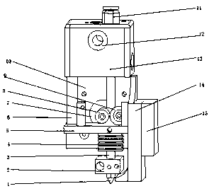
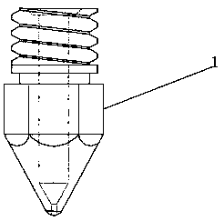
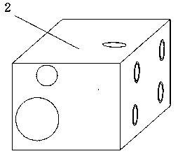
[0021] refer to Figure 1-4 , a head device for a 3D printer, comprising a linear bearing 12 sleeved on the cross optical axis of the 3D printer and a head carrier 13 sleeved on the linear bearing 12, the bottom of the head carrier 13 is connected to The column 6 is connected with a motor fixing frame, and the motor fixing frame includes a motor upper bracket 10 and a motor lower bracket 5 positioned on the outer wall of the motor upper bracket 10, the same motor 7 is fixed on the motor upper bracket 10 and the motor lower bracket 5, The output shaft of the motor 7 is sleeved with a feed wheel 8, and the outer wall of the motor lower bracket 5 is connected wi...


PUM


Abstract

The invention discloses a head device for a 3D printer. The printer comprises a linear bearing which sleeves a cross optical shaft of the 3D printer and a head carrier which sleeves the linear bearing, the bottom of the head carrier is connected with a motor fixing frame through a connecting column, the motor fixing frame comprises a motor upper bracket and a motor lower bracket on an outer wall of one side of the motor upper bracket, the same motor is fixed on the motor upper bracket and the motor lower bracket, the output shaft of the motor is sleeved with a feeding wheel, the outer wall ofthe motor lower bracket is connected with a driven wheel which meshes with the feeding wheel, the bottom of the motor lower bracket is connected with a hollow throat, the upper outer wall of the hollow throat is provided with heat dissipating blocks which are equidistantly distributed, and the lower portion of the hollow throat is sleeved with a heating block. The device runs more smoothly, can quickly load and unload materials, has smooth silk output, feeds a silk at the proximal end, is beneficial to the withdrawal of the consumables, can reduce the drawing phenomenon, and has better printing effect, the hollow throat is durable, and the heat dissipation performance is good.

Description

technical field [0001] The invention relates to the technical field of 3D printing, in particular to a head device for a 3D printer. Background technique [0002] Rapid Prototyping Manufacturing (RPM for short) is a kind of rapid prototyping technology. It is a technology based on digital model files and using bondable materials such as powdered metal or plastic to construct objects by layer-by-layer printing. RPM printing is usually achieved with digital technology material printers. It is often used to make models in the fields of mold manufacturing and industrial design, and is gradually used in the direct manufacture of some products. There are already parts printed using this technology. The technology has applications in jewelry, footwear, industrial design, architecture, engineering and construction (AEC), automotive, aerospace, dental and medical industries, education, geographic information systems, civil engineering, firearms, and others. [0003] At present, dom...

Claims


Application Information

Patent Timeline
IPC IPC(8): B29C64/209B29C64/20B29C64/321B33Y30/00B33Y40/00
CPCB29C64/20B29C64/209B29C64/321B33Y30/00B33Y40/00
Inventor 张永健
Owner 河南沃思智能科技有限公司
Learn More