Continuous diffusion furnace and its ventilation method

A technology of diffusion furnace and furnace body, which is applied in the direction of diffusion/doping, chemical instruments and methods, crystal growth, etc. It can solve the problems of uneven distribution of gas field, blockage of intake pipe, etc., achieve uniform PN junction, avoid blockage, and benefit The effect of uniformity

Inactive Publication Date: 2013-07-31
SHANGHAI XUKANG ELECTRONICS TECH
View PDF4 Cites 2 Cited by
  • Summary
  • Abstract
  • Description
  • Claims
  • Application Information

AI Technical Summary

Problems solved by technology

[0004] The object of the present invention is to provide a continuous diffusion furnace and its ventilation method to solve the problems of uneven distribution of the gas field in the diffusion furnace and easy blockage of the inlet pipe

Method used


Image

  • Continuous diffusion furnace and its ventilation method
  • Continuous diffusion furnace and its ventilation method
  • Continuous diffusion furnace and its ventilation method

Examples


Embodiment Construction

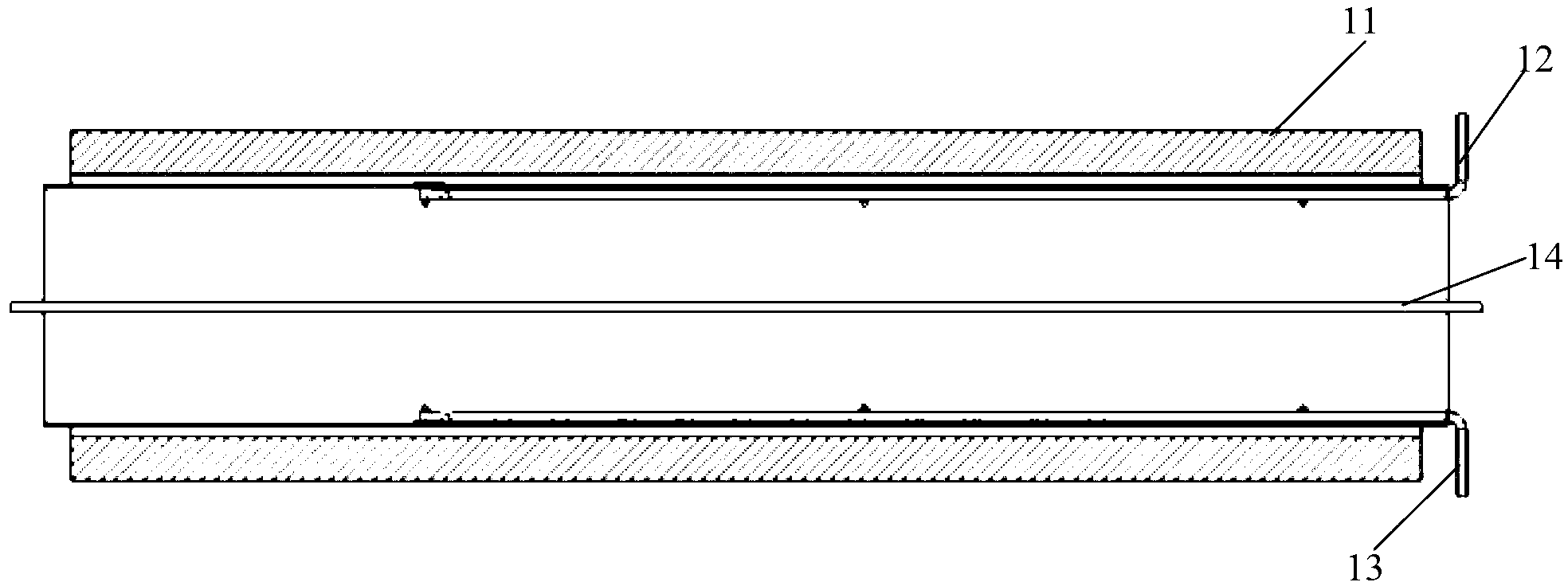
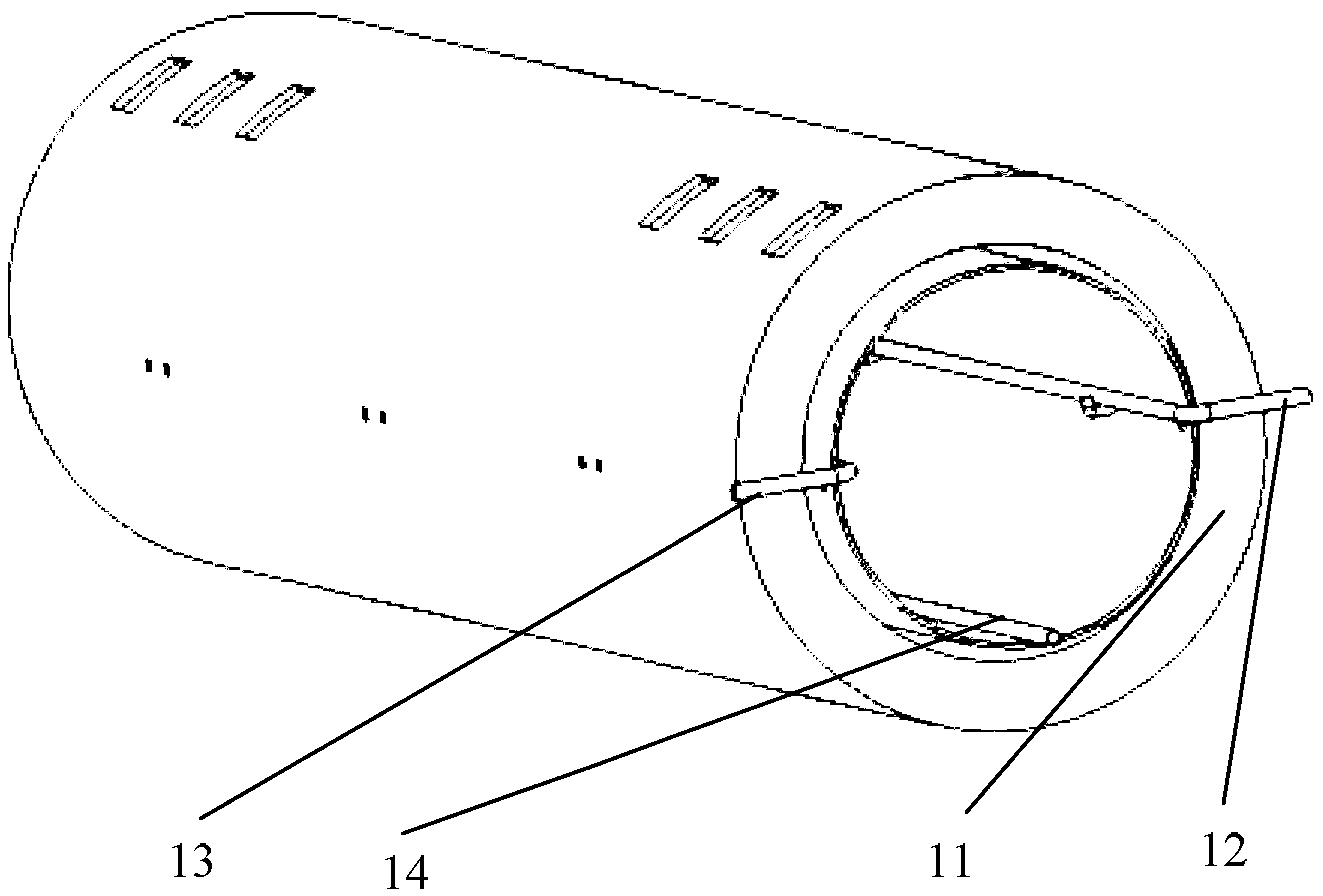
[0026] A continuous diffusion furnace and its ventilation method proposed by the present invention will be further described in detail below in conjunction with the accompanying drawings and specific embodiments. Advantages and features of the present invention will be apparent from the following description and claims. It should be noted that all the drawings are in a very simplified form and use imprecise scales, and are only used to facilitate and clearly assist the purpose of illustrating the embodiments of the present invention.
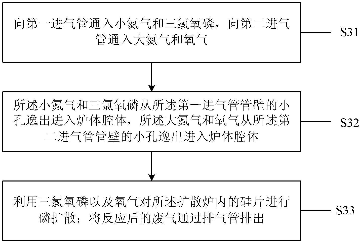
[0027] The core idea of ​​the present invention is that in the continuous diffusion furnace provided by the present invention, the two gases that are likely to react enter the furnace body through the first inlet pipe and the second inlet pipe respectively, so as to prevent the two gases from reacting when they are mixed in the pipe. Pipeline blockage caused by different gases; different gases escape through a number of small holes evenly opened...


PUM


Abstract

The invention provides a continuous diffusion furnace which comprises a furnace body with two open ends, a first air inlet pipe with an open end and an enclosed end, a second air inlet pipe with an open end and an enclosed end, and an exhaust pipe which is fixedly arranged on the inner wall of the furnace body chamber, wherein the first air inlet pipe is fixedly arranged on the inner wall of the furnace body chamber; the wall of the first air inlet pipe is uniformly provided with several small holes which are far from the inner wall of the furnace body chamber; the second air inlet pipe is fixedly arranged on the inner wall of the furnace body chamber; the wall of the second air inlet pipe is uniformly provided with several small holes which are far from the inner wall of the furnace body chamber; two ends of the exhaust pipe are both opened; negative pressure is applied on the two ends of the exhaust pipe; and the wall of the exhaust pipe is provided with several small holes which are far from the inner wall of the furnace body chamber. By the adoption of the ventilation method of the continuous diffusion furnace, consistent density of reactant gases around silicon chips in the same batch is realized. PN junctions of the silicon chips are uniform. And two breather pipes are simultaneously used for ventilation, so as to avoid obstruction of breather pipe holes.

Description

technical field [0001] The invention relates to the technical field of semiconductor manufacturing, in particular to a continuous diffusion furnace and a ventilation method thereof. Background technique [0002] In the production process of crystalline silicon solar cells, diffusion is an important process for preparing PN junctions. The existing technology uses a high-temperature closed-tube diffusion furnace to complete this process. Diffusion technology is an important process in monocrystalline silicon and polycrystalline silicon solar cells. Its purpose is to form the emitter region with the opposite conductivity type of the substrate, thereby forming a PN junction. Usually monocrystalline silicon and polycrystalline silicon solar cells use P-type substrates, phosphorus oxychloride liquid source diffusion, and a diffuse N-type emitter region is formed through a series of chemical reactions and phosphorus atom diffusion processes. The diffusion process of solar cells re...

Claims


Application Information

Patent Timeline
Patent Type & Authority Applications(China)
IPC IPC(8): C30B31/10C30B31/16
Inventor 陆利新郑荣豪陈荣莲
Owner SHANGHAI XUKANG ELECTRONICS TECH
Why Eureka
Try Eureka