
An oil-free screw compressor

A compressor and oil screw technology, which is applied in the field of oil-free screw compressors, can solve the problems of noise leakage, noise leakage to the outside, noise increase, etc., and achieve the effect of sufficient cooling and noise reduction

Active Publication Date: 2013-07-31
코벨코컴프레서가부시키가이샤
View PDF7 Cites 0 Cited by
  • Summary
  • Abstract
  • Description
  • Claims
  • Application Information

AI Technical Summary

Problems solved by technology

However, if the cooling performance of the fan is improved, the noise will become louder
In addition, if the opening for air intake / exhaust is enlarged, the noise inside the housing will easily leak to the outside.
In addition, if the cooling air path from the opening to the heat source is ensured, this path will become a propagation path of noise, and noise will easily leak from the opening.

Method used


Image

  • An oil-free screw compressor
  • An oil-free screw compressor
  • An oil-free screw compressor

Examples


Embodiment Construction

[0065] Hereinafter, preferred embodiments of the present invention will be described with reference to the drawings.

[0066] (Structure of oil-free screw compressor)

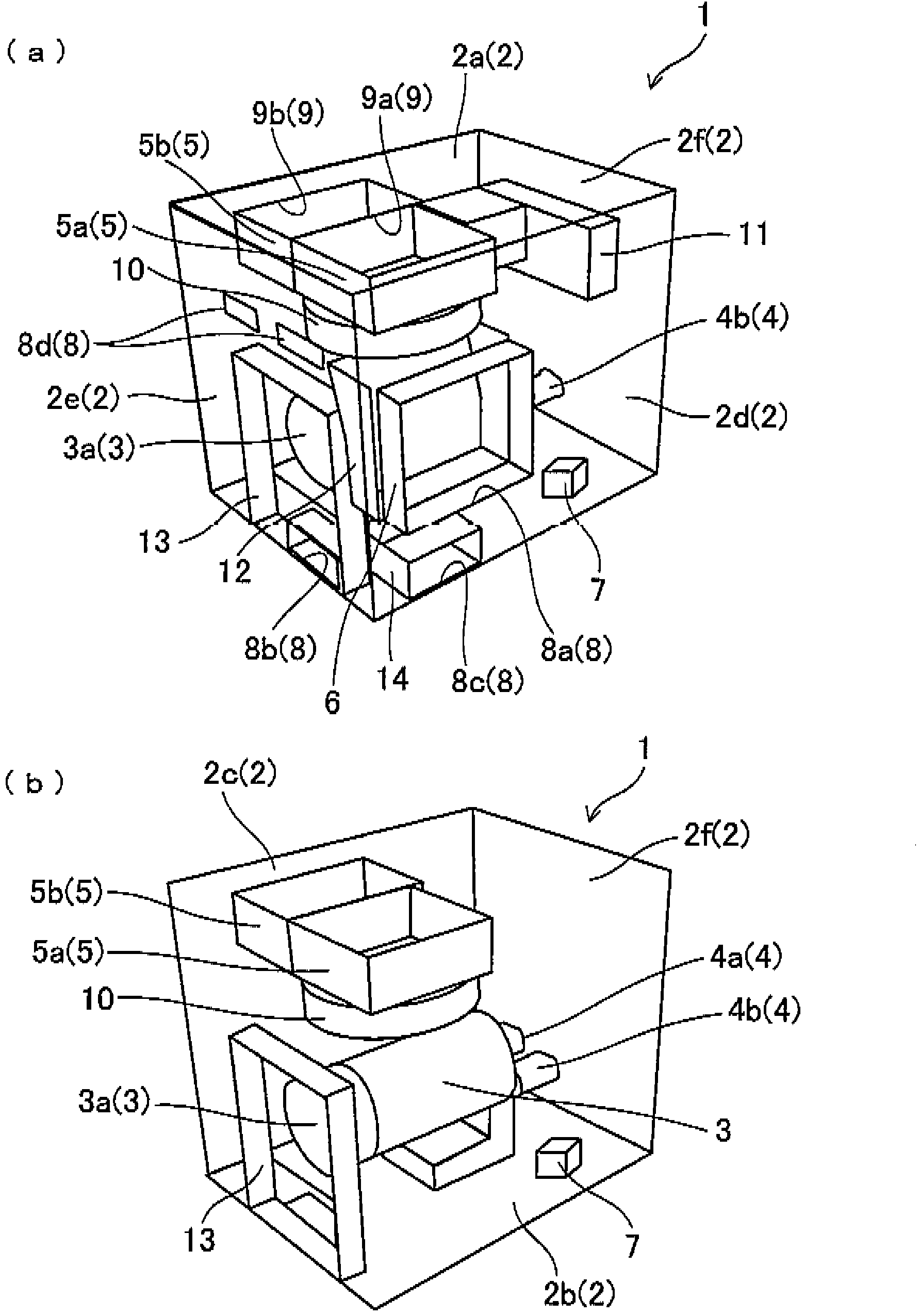
[0067] The oil-free screw compressor 1 of this embodiment cools the air compressed by the compressor main body 4 driven by the electric motor 3 with the gas cooler 5, and cools the lubricating oil used in the drive system of the compressor main body 4 with oil. device 6 for cooling, such as figure 1 As shown, there is a hexahedral housing 2 with built-in electric motor 3 , compressor body 4 , gas cooler 5 and oil cooler 6 . In addition, in figure 1 In (b), the upper surface 2a, the right side 2e, the back surface 2d of the casing 2, the oil cooler 6, the suction duct 11 described later, the suction port communicating with the suction duct 11, and the oil cooler are omitted. The diagram of the opening-side duct 12 for equipment and the opening-side duct 14 for internal equipment.

[0068] The electric motor ...


PUM


Abstract

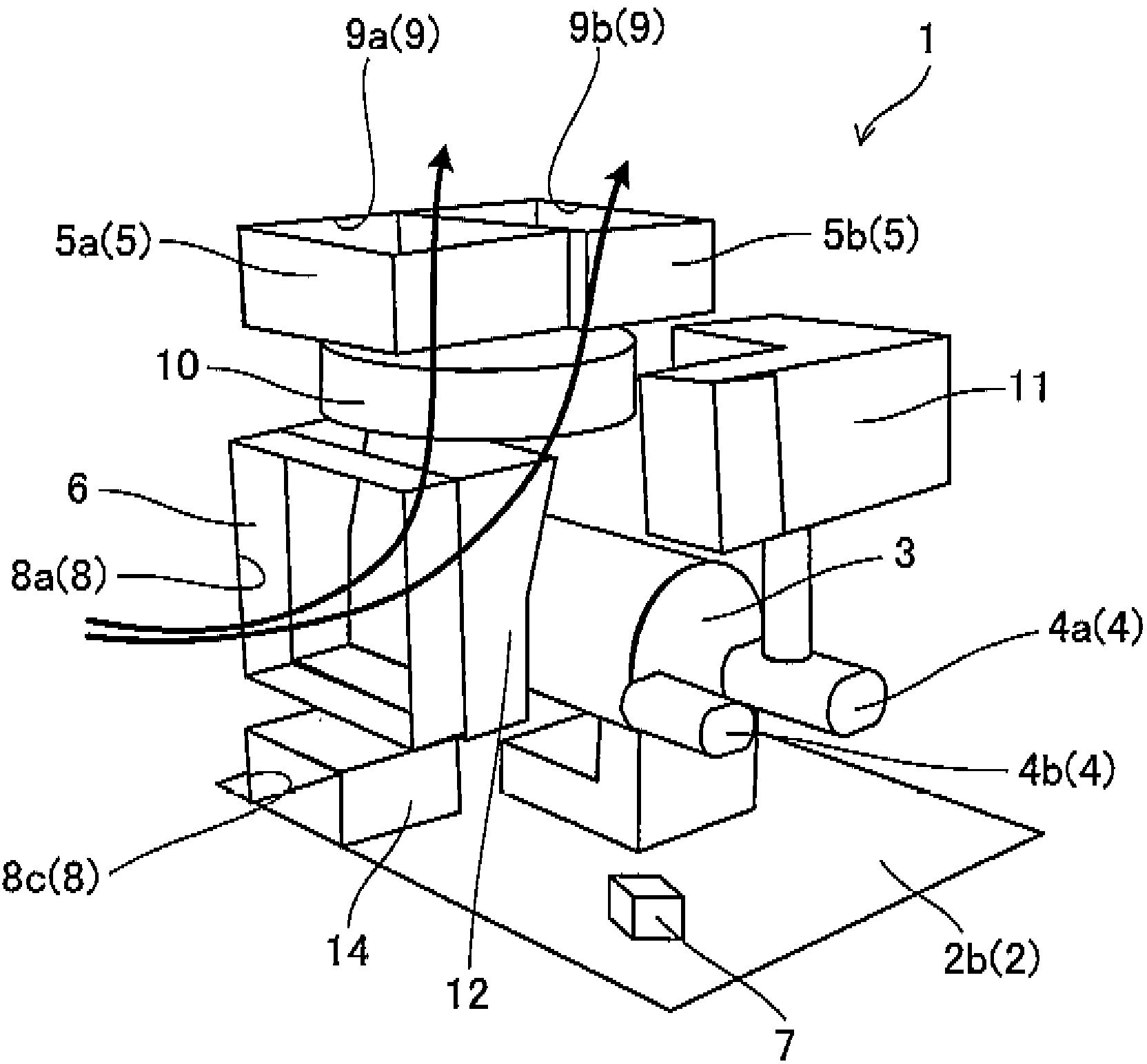
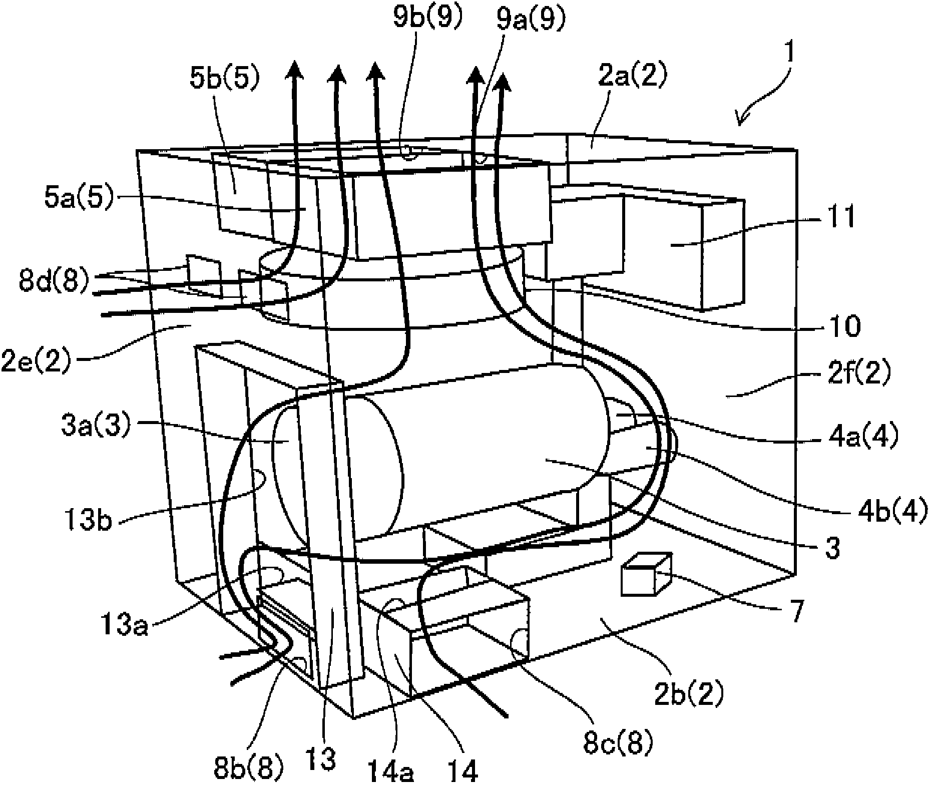
The invention provides an oil-free screw compressor capable of fully cooling a heat source while reducing noise leaked externally. Cooling air introduced from an opening portion (8a) used for an oil cooler into a housing (2) successively passes the oil cooler (6), a fan (10), and an air cooler (5) and then is expelled out from an opening portion (9) used for exhaust. In addition, cooling air introduced from an opening portion (8b) used for a motor into the housing (2) successively passes a motor fan (3a), a motor (3), the fan (10), the air cooler (5) and then is expelled out from the opening portion (9) used for exhaust. In addition, cooling air introduced from an opening portion (8c) used for a inner device into the housing (2) successively passes a solenoid valve (7), the fan (10), the air cooler (5) and then is expelled out from the opening portion (9) used for exhaust.

Description

technical field [0001] The invention relates to an air-cooled oil-free screw compressor. Background technique [0002] Patent Document 1 discloses an oil supply type air compressor as a screw compressor used in an air source factory or the like. In this air compressor, the air flow is formed by the cooling fan installed in the casing, and the motor, the gas cooler, and the oil cooler are sequentially cooled by the cooling air introduced from the opening of the casing, and the cooled air is transferred from the exhaust vent. However, in this structure, the air after cooling the motor and the gas cooler will heat up, and the oil cooler cannot be sufficiently cooled. Not only that, the air flow is limited to the right half where the motor, etc. are located, and cannot cool the left side. device of. [0003] In addition, Patent Document 2 discloses an oil-supply type screw compressor in which the casing is divided into two chambers, airflow is formed by fans installed in each...

Claims


Application Information

Patent Timeline
Patent Type & Authority Applications(China)
IPC IPC(8): F04C18/16F04C29/04
Inventor 矢野宜男平田和也木村康正
Owner 코벨코컴프레서가부시키가이샤
Learn More