
Vehicle headlamp for generating a main light distribution and an additional light distribution

A technology of auxiliary lights and auxiliary lighting, which is applied in the direction of motor vehicles, headlights, electric light sources, etc., and can solve the problems of no longer being recognizable.

Active Publication Date: 2013-07-31
ZKW GRP GMBH
View PDF7 Cites 5 Cited by
  • Summary
  • Abstract
  • Description
  • Claims
  • Application Information

AI Technical Summary

Problems solved by technology

However, in the dark, when the main light emitting unit, usually the dipped beam, is switched on, the luminous area of ​​the auxiliary light emitting unit is illuminated by the main light and is no longer recognizable

Method used


Image

  • Vehicle headlamp for generating a main light distribution and an additional light distribution
  • Vehicle headlamp for generating a main light distribution and an additional light distribution
  • Vehicle headlamp for generating a main light distribution and an additional light distribution

Examples


Embodiment Construction

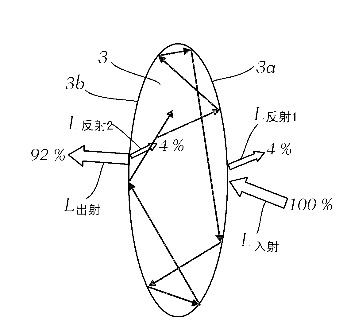
[0035] FIG. 1 shows a lens 3 for a main light lighting unit, for example for a low beam lighting unit, which is embodied as a projection module and has, for example, a light source, a reflector and a projection lens 3 .

[0036] Light L irradiated onto the light incident surface 3a of the lens from a not shown light source, if necessary via a likewise not shown reflector 入射 part is reflected (L 反射1 ), for example about 4% of the incident light flux is reflected. In addition, the light is reflected on the surface 3b when exiting the lens 3 through the light exit surface 3b (L 反射2 ), and additional reflections occur internally. Again these reflections add up to about 4%, so that about 92% of the incident ray exits the lens (L 出射 ) and is used to generate the main light distribution.

[0037] Due to these reflections on the one hand light is lost and on the other hand the lens appears bright (illuminated).

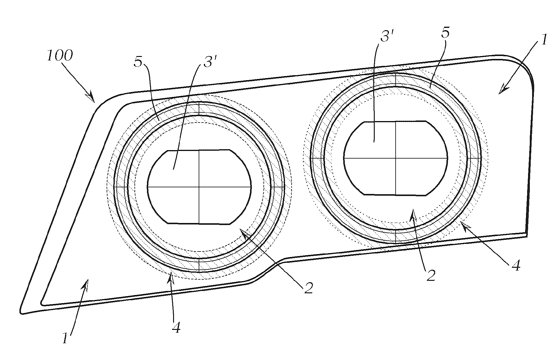
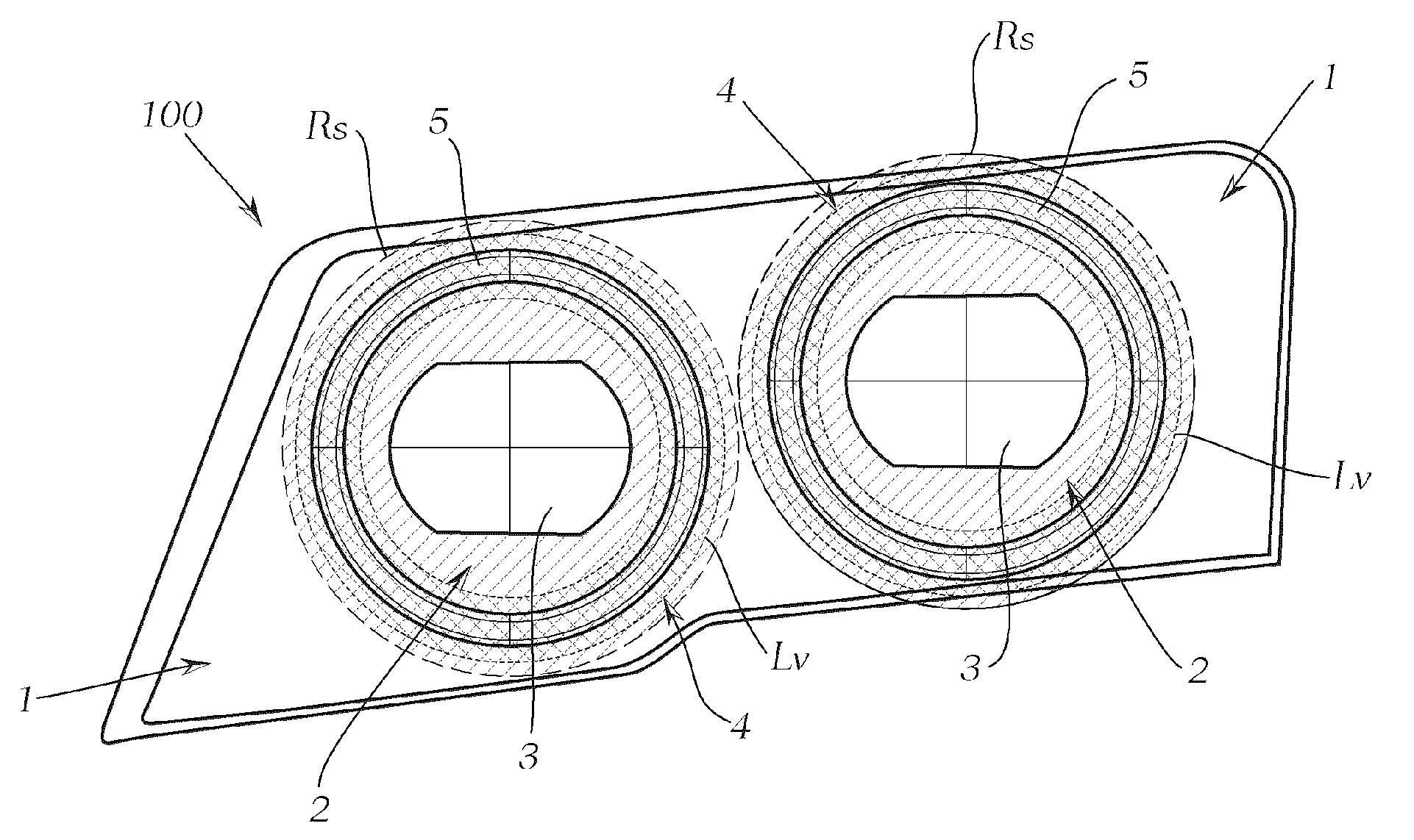
[0038]FIG. 2 shows a vehicle headlight 100 with two lighting module...


PUM


Abstract

The invention relates to a vehicle headlamp. The vehicle headlamp comprises a light emitting unit which produces main light and which comprises a light source and lenses. When the light emitting unit is mounted in a vehicle, the lenses are used as main light distribution so that the light emitted by the light source is projected as main light distribution on the area ahead of vehicle. A supplementary light emitting unit for generating supplementary light distribution is also included. The supplementary light emitting unit is arranged in a manner in which the light or the area of the light of the supplementary light emitting unit is close to the lens of the main light emitting unit. According to the invention, anti-reflection coating is disposed on the at least prost of the light incoming surface of the lens of the main light emitting unit. And / or anti-reflection coating is disposed on the at least prost of the light outgoing surface of the lens of the main light emitting unit. And the supplementary light emitting unit is connected in the operation of the main light.

Description

technical field [0001] The present invention relates to an automobile headlight, which comprises at least one light-emitting unit for producing the function of a main light, wherein the light-emitting unit is composed of at least one light source and at least one lens such as a projection lens (condensing lens), so The at least one lens images the light emitted by the at least one light source as the main light distribution into the area in front of the vehicle as the main light distribution in the state where the light-emitting unit is installed in the vehicle, and the headlight also includes a light distribution designed for At least one auxiliary light-emitting unit for generating auxiliary light distribution, wherein the at least one auxiliary light-emitting unit is arranged so that the light-emitting or light-emitting area of ​​the auxiliary light-emitting unit is optically close to the main light-emitting unit during the operation of the auxiliary light-emitting unit The...

Claims


Application Information

Patent Timeline
IPC IPC(8): F21S8/10F21V5/04G02B1/11F21W101/02F21W107/10
CPCB60Q2400/30F21S48/1283B60K11/04B60Q1/0047B60Q1/38B60Q1/28F21S41/275B60Q1/381
Inventor M.丹纳A.鲁格
Owner ZKW GRP GMBH
Learn More