Gas turbine combustor and operating method thereof

A gas turbine and burner technology, which is applied in combustion methods, gas turbine devices, burners, etc., can solve problems such as reducing the discharge of unburned parts, and achieve the effect of ensuring combustion stability

Active Publication Date: 2013-07-31
MITSUBISHI POWER LTD
View PDF8 Cites 10 Cited by
  • Summary
  • Abstract
  • Description
  • Claims
  • Application Information

AI Technical Summary

Problems solved by technology

[0009] The Japanese Patent Application Publication No. 2003-148734 and Japanese Patent Application Publication No. 2011-075172 disclose the structure of multiple burners, but these known examples do not aim at reducing the discharge of unburned parts under the partial load condition of the gas turbine. and technology for suppressing the temperature rise of the lining metal

Method used


Image

  • Gas turbine combustor and operating method thereof
  • Gas turbine combustor and operating method thereof
  • Gas turbine combustor and operating method thereof

Examples


Embodiment 1)

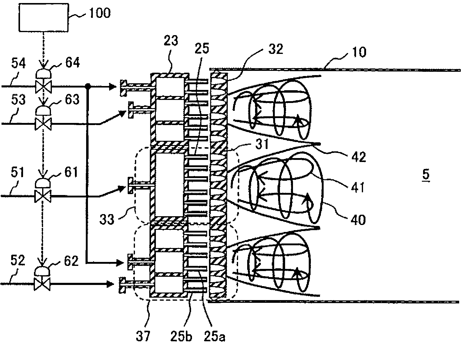
[0031] use Figure 1 to Figure 3 A gas turbine combustor and a gas turbine combustor operating method according to a first embodiment of the present invention will be described.

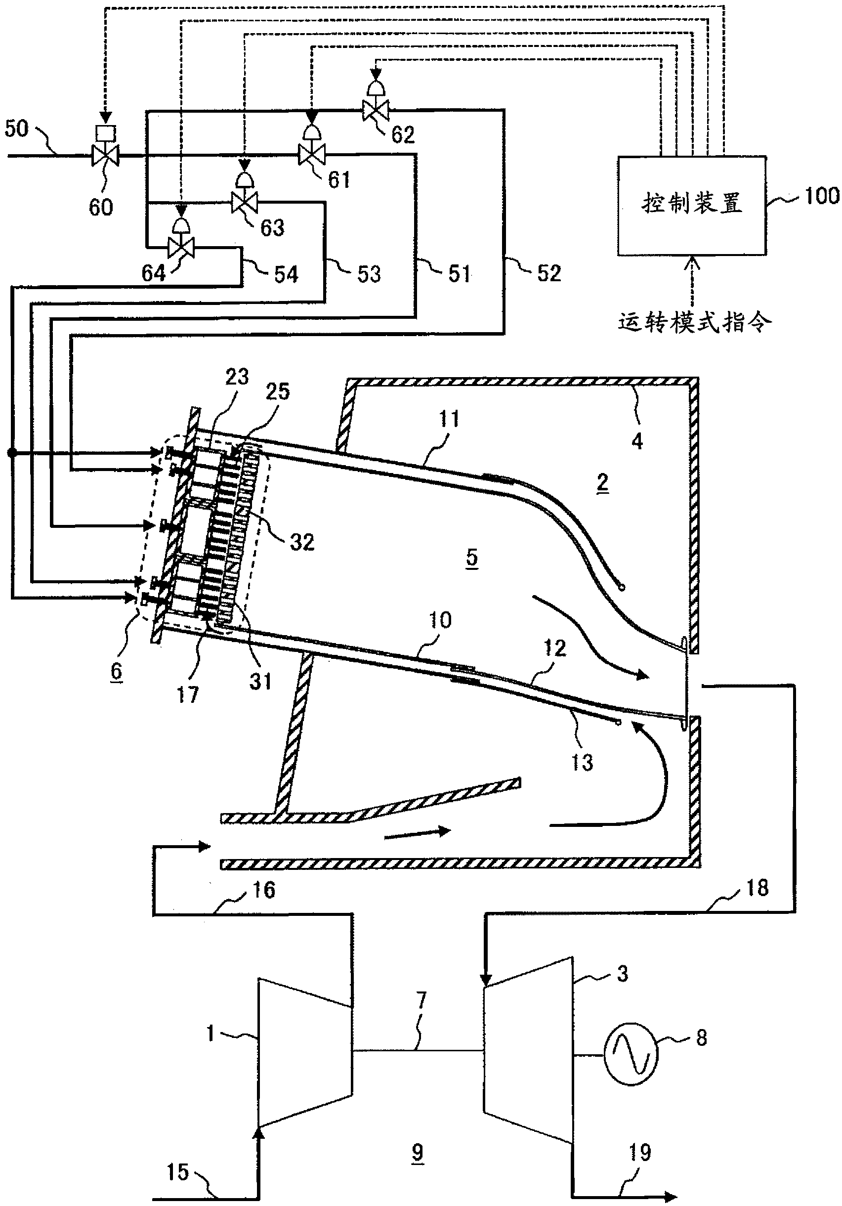
[0032] figure 1 It is a systematic diagram showing the overall configuration of a gas turbine facility for power generation.

[0033] exist figure 1 In the gas turbine facility 9 shown, the gas turbine for power generation is composed of: a compressor 1 that pressurizes intake air 15 to generate high-pressure air 16; A gas turbine combustor 2 generating high-temperature combustion gas 18; a steam turbine 3 driven by the high-temperature combustion gas 18 generated by the gas turbine combustor 2; a generator 8 driven to rotate by the steam turbine 3 to generate electric power; the compressor 1, steam turbine 3 And the shaft 7 to which the generator 8 is connected as one.

[0034] Furthermore, the gas turbine combustor 2 is accommodated inside the casing 4 . In addition, the gas turbine combustor ...

Embodiment 2)

[0095] use Figure 7 as well as Figure 8 A gas turbine combustor 2 according to a second embodiment of the present invention will be described.

[0096] The gas turbine combustor 2 of the present embodiment and Figure 1 to Figure 5 The gas turbine combustors 2 of the first embodiment shown are the same in basic structure and effect, so the description of the common parts will be omitted, and the different parts will be described below.

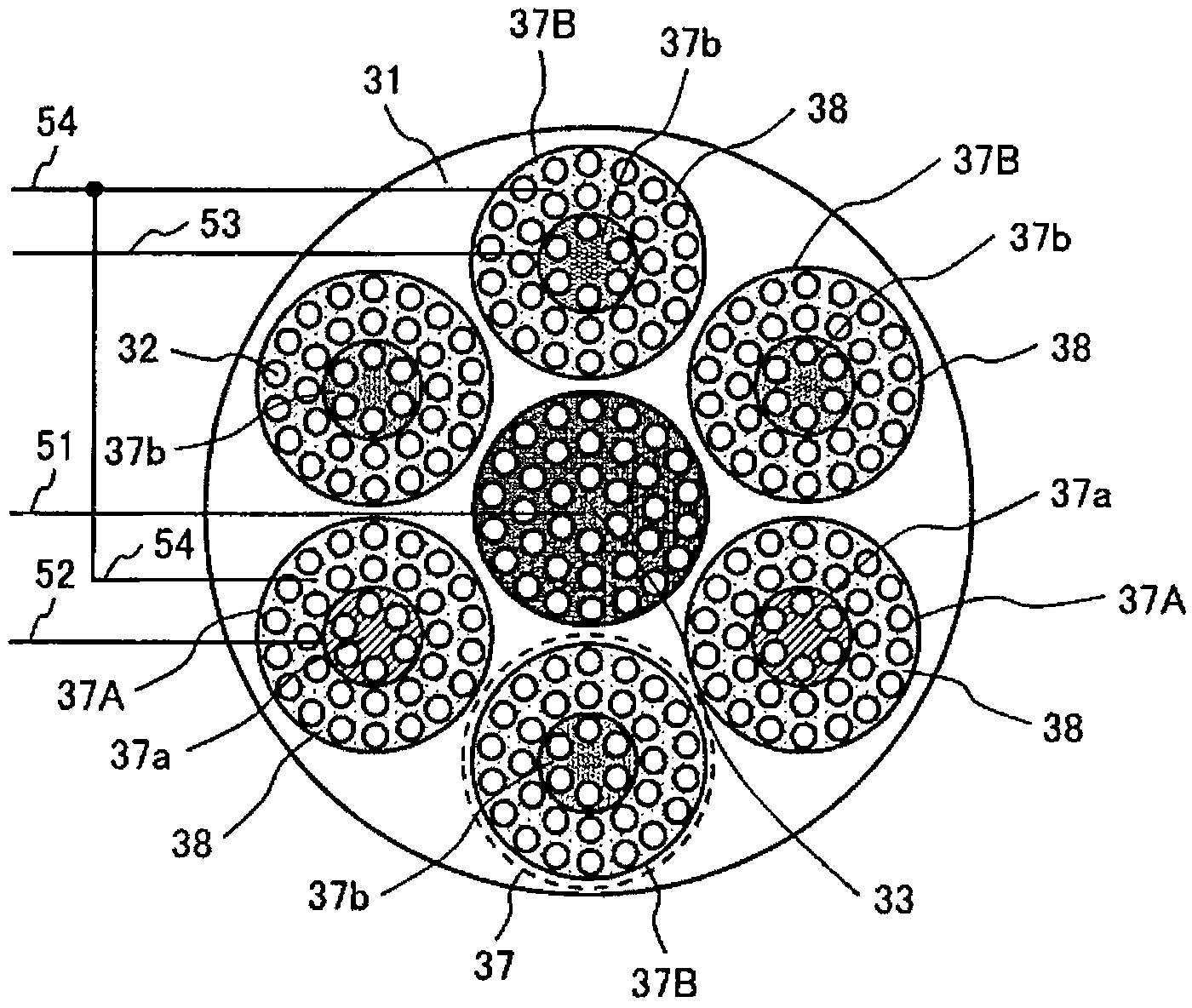
[0097] Figure 7 The gas turbine combustor 2 of the present embodiment shown is a front view of the burner viewed from the combustion chamber, and for each burner, a region supplied with fuel by the same fuel system is shown separately.

[0098] exist Figure 7 In the gas turbine combustor 2 shown in this embodiment, as Figure 7 As shown, six outer burners 37 are provided in the peripheral area of ​​the air orifice plate 31, including: on both sides of the central burner 33 located in the center of the air orifice plate 31, which are o...

Embodiment 3)

[0109] use Figure 9 as well as Figure 10 A gas turbine combustor 2 according to a third embodiment of the present invention will be described.

[0110] The gas turbine combustor 2 of the present embodiment and Figure 1 to Figure 5 The gas turbine combustors 2 of the first embodiment shown are the same in basic structure and effect, so the description of the common parts will be omitted, and the different parts will be described below.

[0111] Figure 9 The gas turbine combustor 2 of the present embodiment shown is a front view of the burner viewed from the combustion chamber, and for each burner, a region supplied with fuel by the same fuel system is shown separately.

[0112] exist Figure 9 In the gas turbine combustor 2 shown in this embodiment, as Figure 9 As shown, six outer burners 37 are arranged in the peripheral area of ​​the air orifice plate 31 and are configured to include: positions on both sides of the obliquely lower side (the side of the cross-fire tu...


PUM


Abstract

An object of the present invention is to provide a gas turbine combustor and an operating method of the gas turbine combustor to allow the gas turbine combustor to ensure combustion stability in the entire range of load conditions of the gas turbine and reduce the generation of unburned combustibles and an increase in liner metal temperature at the same time in partial load conditions of the gas turbine. The gas turbine combustor comprises: a chamber supplied with fuel and air; an air hole plate located in an upstream side of the chamber, forming a plurality of air holes for supplying the air; and a multi-burner having a plurality of burners provided with fuel nozzles. The multi-burner is made up of a center burner disposed in the center and a plurality of outer burners around the center burner, the outer burners are divided into inner fuel nozzles and outer fuel nozzles to separately supply fuel through fuel systems, and the fuel is supplied to the fuel nozzles in the center burner or to the fuel nozzles in the center burner and the inner fuel nozzles in the outer burners disposed around the center burner in a partial load condition in which the load is lower than that of when all the fuel systems are used to supply fuel.

Description

technical field [0001] The present invention relates to a gas turbine combustor and a method for operating the gas turbine combustor. Background technique [0002] From the viewpoint of environmental protection, gas turbines are required to further reduce NOx. [0003] A premix combustor is mentioned as one means for reducing NOx in a gas turbine combustor, but in this case, there is concern about a backfire phenomenon in which flame enters the inside of the premixer. [0004] Japanese Patent Application Laid-Open No. 2003-148734 discloses a gas turbine combustor comprising a fuel nozzle for supplying fuel to the combustion chamber and an air hole for supplying air located downstream of the fuel nozzle. The nozzle for fuel combustion in which the outlet hole and the air hole are arranged coaxially is constituted, and a gas turbine combustor having both backfire resistance and low NOx combustion is disclosed. [0005] In addition, Japanese Patent Application Laid-Open No. 2...

Claims


Application Information

Patent Timeline
Patent Type & Authority Applications(China)
IPC IPC(8): F23R3/28F23R3/12
CPCF23R3/34F23N2041/20F23D2900/00015F23N1/002F23R3/04F23R3/28F23N2241/20
Inventor 三浦圭佑小金泽知己阿部一几斋藤武雄
Owner MITSUBISHI POWER LTD
Why Eureka
Try Eureka