Vacuum filling and sealing device for warhead

A warhead and potting technology, which is applied in the field of equipment for potting and sealing weapon warheads, can solve the problems of the potting glue cannot continue to be potted, the potting glue is difficult to be filled in place, and the amount of the warhead is reduced. The effect of charging process cost, reducing charging cost and improving safety performance

Inactive Publication Date: 2013-07-31
INST OF CHEM MATERIAL CHINA ACADEMY OF ENG PHYSICS
View PDF4 Cites 11 Cited by
  • Summary
  • Abstract
  • Description
  • Claims
  • Application Information

AI Technical Summary

Problems solved by technology

For the potting of small gaps, it is difficult to fill the potting glue in place, and it cannot fill 50% of the required amount within 5 to 6 hours. After a longer time, the process flow time of the potting glue has passed, and the potting glue cannot continue. potting
In order to avoid the safety problem of the gap between the drug and the shell and the difficulty of filling the gap, many warheads are charged with the pre-prepared combined powder column and potting glue at the same time, which will greatly reduce the warhead loading. The amount of charge affects the power of the warhead, and greatly increases the complexity of the charge preparation process and the charge cost, and this filling method cannot be realized for warheads with irregular geometric dimensions and mouths smaller than the main body size
In the method of vacuum injection filling and sealing, putting the entire warhead and charge into the vacuum to inject the potting glue requires a large vacuum device, and at the same time there is no pressure injection with external pressure, although it can greatly improve the potting performance. The efficiency of glue injection shortens the potting time, but this method requires a large vacuum device, so it is difficult to achieve

Method used


Image

  • Vacuum filling and sealing device for warhead
  • Vacuum filling and sealing device for warhead
  • Vacuum filling and sealing device for warhead

Examples


Embodiment Construction

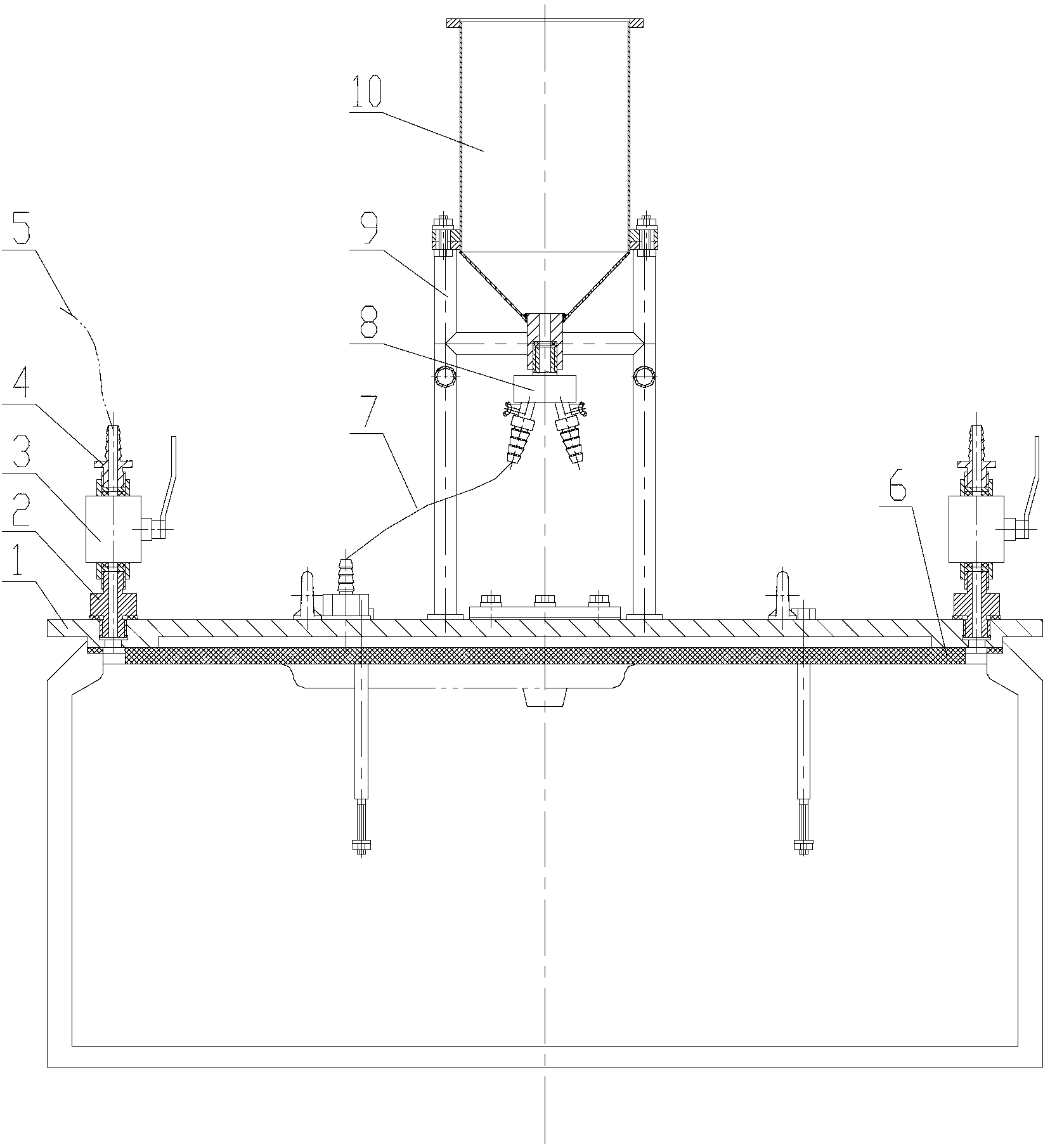
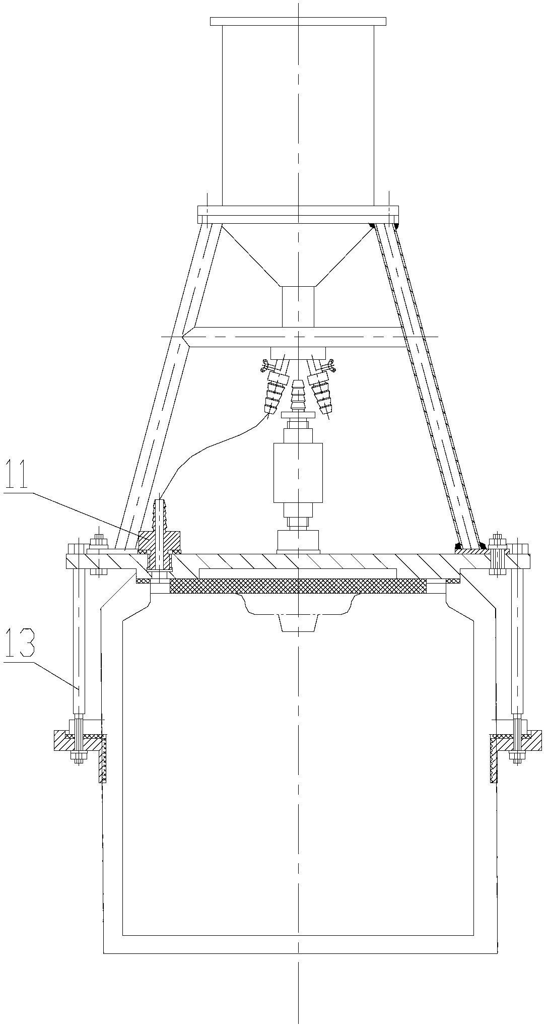
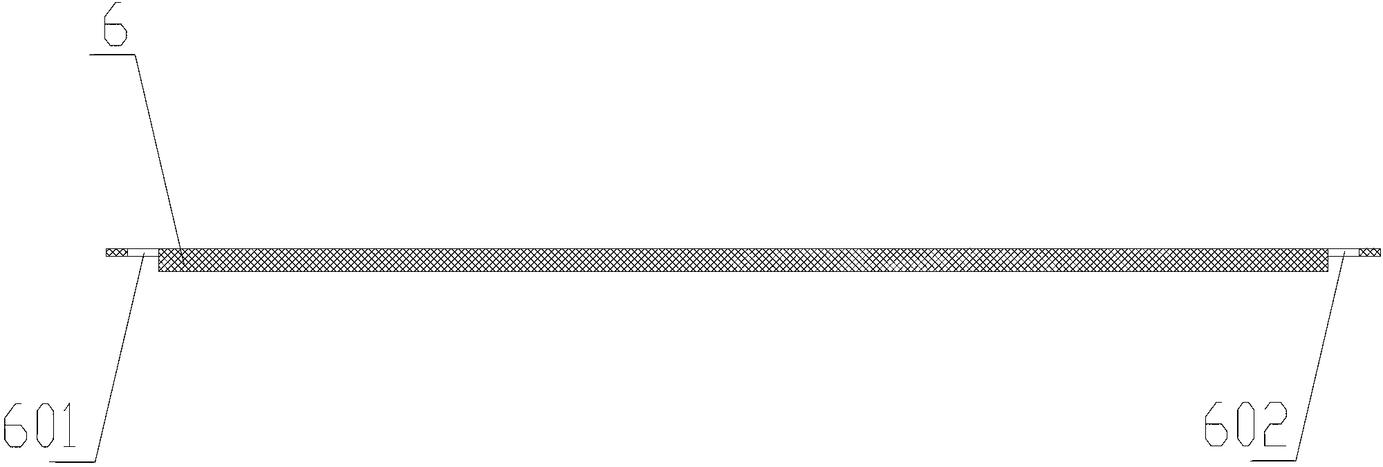
[0026] figure 1 is the front view of the warhead vacuum potting device, figure 2 yes figure 1 Side view of the warhead vacuum potting setup shown. combine figure 1 and figure 2 The combat head vacuum potting device of the present invention will be described in detail. The vacuum potting device for the warhead includes a potting device body and vacuum equipment arranged on the potting device body. The potting device body includes a cover plate 1 used in conjunction with the mouth of the warhead shell, a hopper 10 for holding the potting glue, and a fixed hopper 10 is also arranged between the hopper 10 and the cover plate 1 And the hopper support 9 of the cover plate 1, the end of the hopper close to the cover plate is provided with a discharge valve 8, the cover plate 1 is provided with a fastener 13, and the bottom surface of the cover plate 1 is provided with a gasket layer 6. The feeding valve 8 is sealed and connected with the feeding nozzle 11 arranged on the cove...


PUM


Abstract

The invention discloses a vacuum filling and sealing device for a warhead. The vacuum filling and sealing device comprises a filling and sealing device body and vacuum extraction equipment arranged on the filling and sealing device body, wherein the filling and sealing device body comprises a cover plate used with a shell opening part of the warhead, and a hopper used for storing filling and sealing gum; a hopper bracket used for fixing the hopper and the cover plate is also arranged between the hopper and the cover plate; a blanking valve is arranged at one end of the hopper close to the cover plate; and a feeding hole of the hopper is directly connected with the atmosphere. According to the vacuum filling and sealing device, the powder charge shell opening of the warhead is sealed to vacuumize a powder charge cavity body so as to reduce the filling resistance of the filling and sealing gum; and meanwhile, the filling and sealing gum is filled in the vacuum powder charge cavity body and a small gap between powder and a shell by the atmospheric pressure so as to solve the difficult problem that the filling and sealing gum is difficultly filled into the small gap between the powder and the shell.

Description

technical field [0001] The embodiment of the invention relates to a device for potting a warhead of a weapon. Background technique [0002] The warhead is the ultimate damage unit for all kinds of ammunition and missiles to damage targets, and is mainly composed of shells, combat charges, detonators and safety devices. Modern warfare puts forward higher requirements on the killing power or damage efficiency of the warhead, and also requires higher safety performance. [0003] At present, the warhead charge of conventional weapons is usually filled with melt-cast explosives and castable heating-curable explosives. When charging by casting, the heated explosives and organic materials will be flowing liquids at a certain temperature, such as 65°C to 120°C. state, after being mixed and cast into a mold or shell, heated and solidified and cooled to form, this process will have volume shrinkage and looseness (shrinkage); at the same time, due to thermal expansion between the char...

Claims


Application Information

Patent Timeline
Patent Type & Authority Applications(China)
IPC IPC(8): F42B33/02
Inventor 黄勇董青松张明戴明鸿罗观郭朋林
Owner INST OF CHEM MATERIAL CHINA ACADEMY OF ENG PHYSICS
Why Eureka
Try Eureka