Branch cantilever beam vibration generator and power generation method thereof

A technology of vibrating generators and cantilever beams, applied in generators/motors, piezoelectric effect/electrostrictive or magnetostrictive motors, electrical components, etc., can solve problems such as difficulties in power management and improve frequency response characteristics , Improve the effect of frequency domain response characteristics

Inactive Publication Date: 2013-07-31
NANJING UNIV OF AERONAUTICS & ASTRONAUTICS
View PDF1 Cites 14 Cited by
  • Summary
  • Abstract
  • Description
  • Claims
  • Application Information

AI Technical Summary

Problems solved by technology

In the existing technology, if the number of peaks needs to be increased, the cantilever beam generators need to be arranged in an array, which will require multiple energy storage elements (piezoelectric ceramics), resulting in difficulties in power management

Method used


Image

  • Branch cantilever beam vibration generator and power generation method thereof
  • Branch cantilever beam vibration generator and power generation method thereof
  • Branch cantilever beam vibration generator and power generation method thereof

Examples


Embodiment Construction

[0021] The technical solutions of the present invention will be described in detail below with reference to the accompanying drawings.

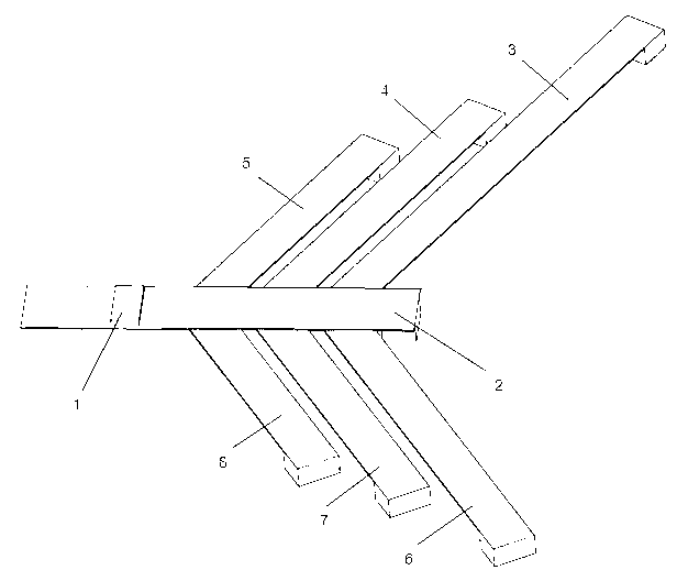
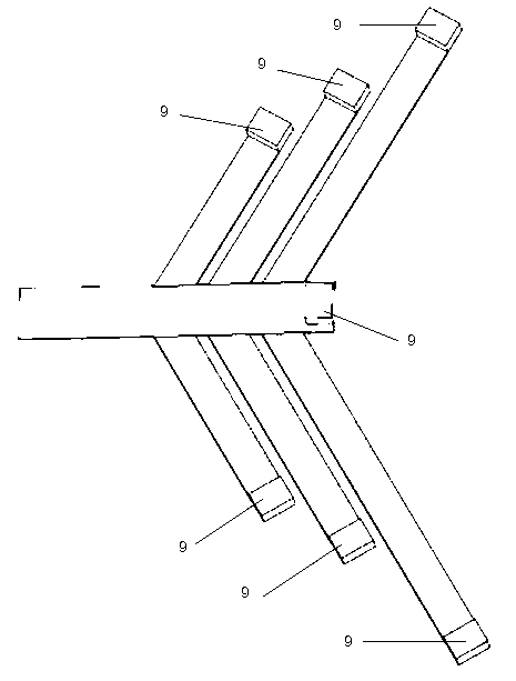
[0022] please combine Figure 1 to Figure 2 As shown, the bifurcated cantilever beam vibration generator of the present invention includes a cantilever beam 2, a first bifurcation 3, a second bifurcation 4, a third bifurcation 5, a fourth bifurcation 6, a fifth bifurcation 7, a Six bifurcations 8, the piezoelectric element 1 arranged (pasted) at the root of the cantilever beam 2 and the counterweight 9 arranged (pasted) at the ends of the foregoing bifurcations 3, 4, 5, 6, 7, 8 and the cantilever beam 2 . The number of middle forks of the bifurcated cantilever beam vibration generator is at least one, and the foregoing bifurcations 3, 4, 5, 6, 7, and 8 can be arranged on one side or both sides of the cantilever beam, and the bifurcations 3, 4, 5, 6, 7, 8 can be placed symmetrically or asymmetrically. At the same time, the positions of the ...


PUM


Abstract

The invention discloses a branch cantilever beam vibration generator which comprises a cantilever beam, a piezoelectric element that is arranged at the root of the cantilever beam and works in a drawing compression mold state, at least one branch arranged on the cantilever beam, and counter weights arranged at the end parts of the branches and the cantilever beam. According to the generator, the branches are integrated at different parts of the cantilever beam, so that the frequency domain response characteristic of the generator is improved; and only the single piezoelectric element is used, so that electric energy management is easy.

Description

technical field [0001] The invention relates to a bifurcated cantilever beam vibration generator and a power generation method thereof, belonging to the technical field of micro power sources. Background technique [0002] The reduction of CMOS circuit size and power consumption, especially the development of ultra-low-power electronics, has greatly promoted the development of wireless sensors, implantable electronic systems, wearable electronic systems, portable electronic systems, etc. Some of these systems are distributed, but the harsh working conditions of these microelectronic products make it difficult for traditional power supply methods such as batteries and wired power supplies to meet their special needs for power supply. In some cases, it is difficult or even impossible to replace batteries. Wireless sensor nodes embedded in concrete structures such as wireless sensor networks with thousands of wireless sensor nodes. Some are portable and require their own power...

Claims


Application Information

Patent Timeline
Patent Type & Authority Applications(China)
IPC IPC(8): H02N2/18
Inventor 胡俊辉张广成
Owner NANJING UNIV OF AERONAUTICS & ASTRONAUTICS
Why Eureka
Try Eureka