
Patsnap Eureka
For R&D, Patsnap Eureka makes reading and utilizing patents & technical documents easy.
Patsnap Eureka AIR
Designed for self-driven R&D workflows. Generate viable solutions, solve complex R&D challenges, empower your innovation with AI.

Patsnap Eureka Materials
Designed for material experts only. Revolutionize your material R&D, from search, analyze, to developing new materials.

TechResearch
Generate reliable direction feasibility study reports for your R&D in just a few steps.

TechSeek
Discover and master advanced knowledge NOW. Basics, ideas, possibilities, all at once.

TechMind
As an expert in R&D Theories, TechMind can generates customized viable solutions instantly.

TechRisk
Analyze your overall solution with one click, know your potential R&D risks in advance.

TechMonitor
Get weekly tech updates, stay abreast of the latest tech innovations and key insights.
Direct smelting process
A direct, metal smelting technology, applied in the field based on molten baths, can solve problems such as difficult mixing requirements
- Summary
- Abstract
- Description
- Claims
- Application Information
AI Technical Summary
Problems solved by technology
Method used
Image

Examples
Embodiment Construction
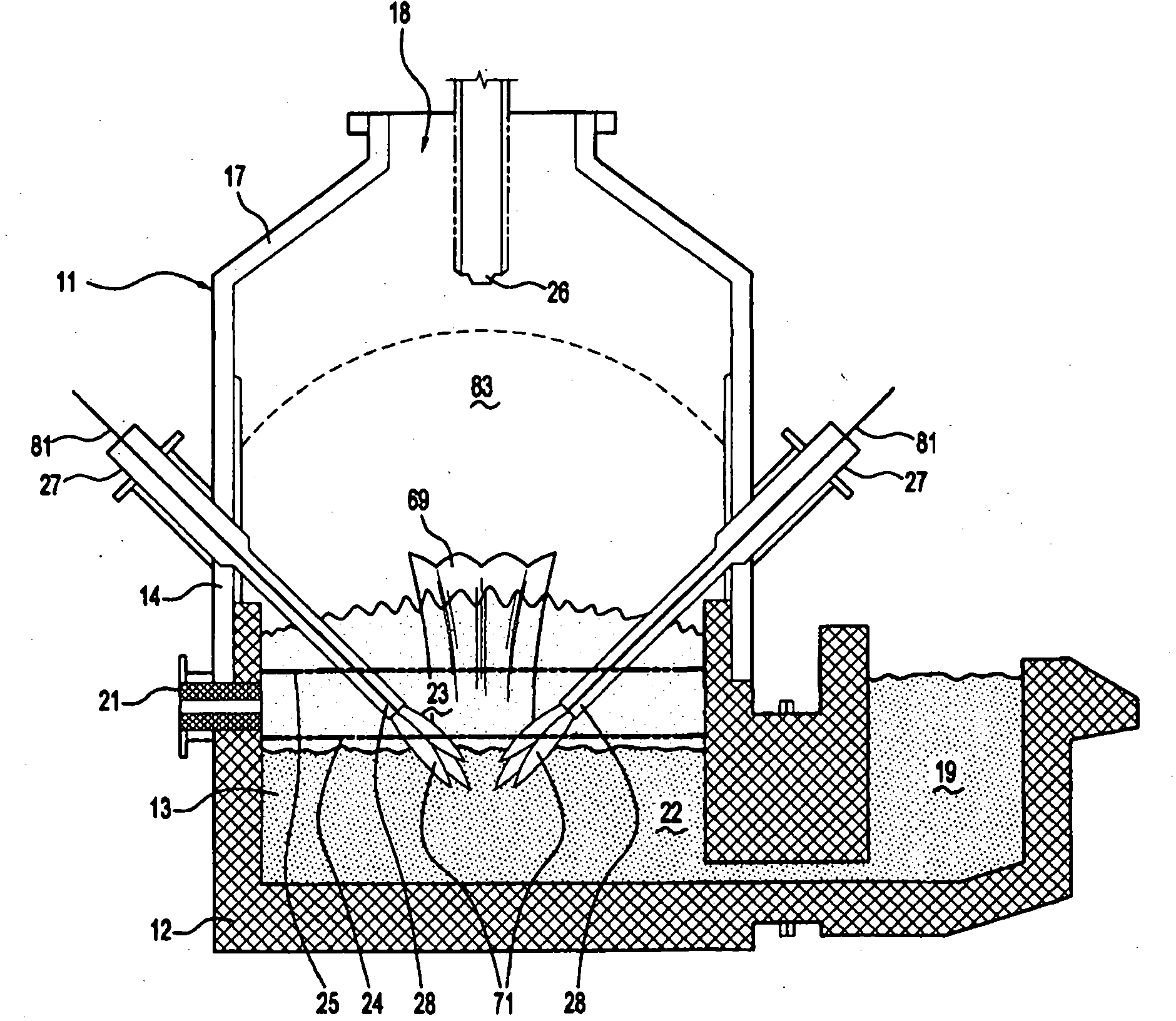
[0068] The following description is for the production of molten iron according to the HIsmelt process in the case of smelting a metal charge in the form of iron ore fines (typically less than 6 mm). However, it should be understood that the invention is not limited to iron ore and can be applied to smelting any metal material in any material form. Ore is an example of a form of metal material. The invention also extends to other forms of metal material, including by way of example partially reduced ores and metal-bearing waste streams.
[0069] Referring to the drawings, there is shown a vessel 11 having a hearth for containing a molten bath of iron and slag, the hearth comprising a base 12 formed of refractory bricks and sides 13, side walls 14 (which are formed from The sides 13 of the hearth are upwardly extending generally cylindrical barrels) and the top 17 . The side walls 14 and top 17 include water cooling plates (not shown) for transferring heat from the side walls...
PUM
 Abstract
Description
Claims
Application Information
 - R&D Engineer
- R&D Manager
- IP Professional
- Industry Leading Data Capabilities
- Powerful AI technology
- Patent DNA Extraction
Browse by: Latest US Patents, China's latest patents, Technical Efficacy Thesaurus, Application Domain, Technology Topic, Popular Technical Reports.
© 2024 PatSnap. All rights reserved.Legal|Privacy policy|Modern Slavery Act Transparency Statement|Sitemap|About US| Contact US: help@patsnap.com