Cable bush

A cable wire and cable technology, which is applied in the direction of electrical components, electrical equipment structural parts, electrical equipment shells/cabinets/drawers, etc., can solve the problems of bushings and cables falling off, and achieve the prevention of cables falling off, simple assembly, and lightening The effect of operational burden

Inactive Publication Date: 2013-07-31
ASAHI DENSHI
View PDF3 Cites 12 Cited by
  • Summary
  • Abstract
  • Description
  • Claims
  • Application Information

AI Technical Summary

Problems solved by technology

[0004] Therefore, if the position of the bushing in the rotation direction of the cable outlet cylinder is not completely aligned, no matter how the bushing is pushed to adjust the position in the front-rear direction, the engaging hole and the engaging protrusion may not be engaged. Causing bushings and cables to come

Method used


Image

  • Cable bush
  • Cable bush
  • Cable bush

Examples


Example Embodiment

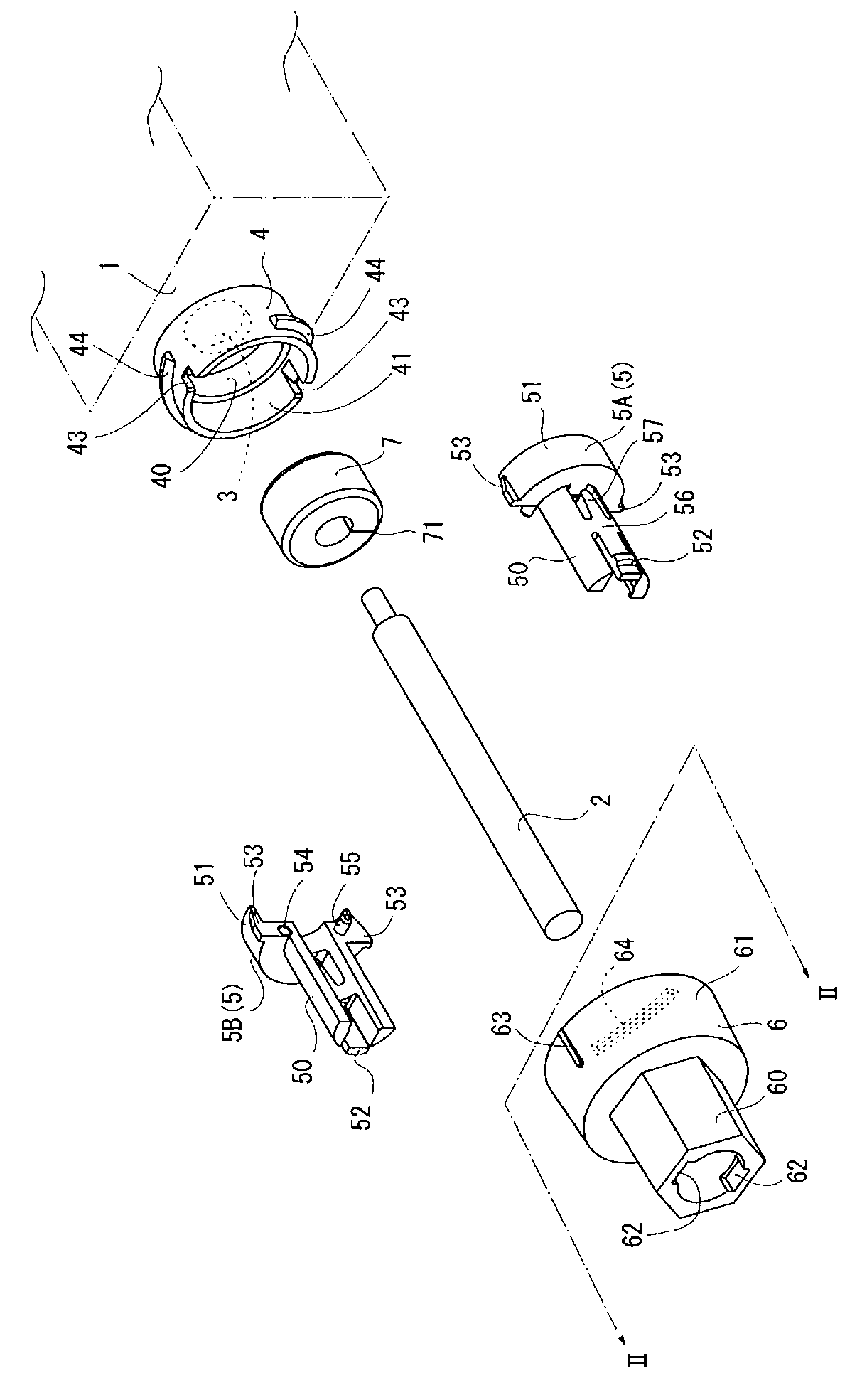
[0050] Such as figure 1 As shown, the cable tie of this embodiment is a bushing that allows the cable 2 to pass through the housing 1. This cable tie includes: a through hole 3; a base member 4; a cable holding member 5; a cover member 6 and a sealing member 7.

[0051] The housing 1 is an outer box made of synthetic resin. For example, an electronic component and an electronic substrate on which the electronic component is mounted are accommodated inside.

[0052] The cable 2 is electrically connected to the electronic components and the electronic substrate in the housing 1, and is connected to external equipment through the cable tie.

[0053] The through hole 3 is a hole provided on the wall surface of the housing 1 for allowing the cable 2 to pass through. The outer diameter of the through hole 3 is larger than the outer diameter of the cable 2, so that the cable 2 can pass through without contacting the through hole 3.

[0054] The base member 4 is formed as a cylindrical body...


PUM


Abstract

Provided is a cable bush that can reliably prevent detachment while simplifying assembly. Slit portions (43) and projecting portions (53) are formed in the cable bush in order to restrict the rotation betweem a base member (4) and fitting portions (51) of a cable-holding portion (5). A base ridge (44) is formed on the outer peripheral surface of the base member (4), and a cap ridge (64) is formed on the inner peripheral surface at the rear end side of a cap member (6). The cap member (6) can be twisted and pressed into the base member (4). In order to restrict the rotation between the cable-holding portion (5) and the cap member (6), and to prevent the detachment of the cap member (6) from the cable-holding portion (5), engaging portions (52) are formed in the cable-holding portion (5), and engagement receptacles (62), with which the engaging portions (52) engage with the engagement receptacles (62) in the rotation direction and the front-back direction, are formed in the cap member (6).

Description

technical field [0001] The invention relates to a cable tie for passing cables through a casing. Background technique [0002] In the prior art, the following cable ties are known. This cable tie has: a cylindrical cable draw-out barrel protruding from the housing; a sealing member inserted into the cable draw-out barrel in a state where the cable is inserted; In the bushing at the opening of the barrel, an engaging hole is formed on the cable outlet barrel, and an engaging protrusion that engages with the engaging hole is formed on the outer peripheral surface of the bushing (refer to Patent Document 1: Japanese Patent Application Laid-Open No. 1-176982 Line 6 on page 8 to line 3 on page 9 and figure 1 ). [0003] However, the position adjustment between the engaging hole of the cable lead-out cylinder and the engaging protrusion of the bushing in the existing cable tie is cumbersome. That is, in order to engage the engaging hole and the engaging protrusion, it is first...

Claims


Application Information

Patent Timeline
IPC IPC(8): H05K7/00F16L5/02H02G3/22
CPCF16L5/02H05K5/069H05K7/00H02G3/22H02G3/083
Inventor 宍户哲夫奈良公宽幕田安博
Owner ASAHI DENSHI
Why Eureka
Try Eureka