Plastic waste gas washing tower

A waste gas washing and plastic technology, which is applied in the separation of dispersed particles, chemical instruments and methods, separation methods, etc., can solve the problems of secondary pollution, air pollution, and affecting the washing effect, and achieve extended service life, good corrosion resistance, The effect of improving the washing quality

Inactive Publication Date: 2013-08-07
ALIBEI PLASTIC STORAGE TANK ANSHAN
View PDF4 Cites 7 Cited by
  • Summary
  • Abstract
  • Description
  • Claims
  • Application Information

AI Technical Summary

Problems solved by technology

[0002] Air pollution and corrosion is a problem that must be solved. In order to solve environmental pollution and air pollution, in the process of industrial waste gas treatment, scrubbers are usually used to deal with pollution factors. The structure of the existing scrubber mainly includes the tower body, which is installed in the tower The exhaust gas inlet at the lower part of the tower body, the exhaust gas outlet at the upper part of the tower body, the tray, packing and spraying device with nozzles arranged in the tower body, the packing of the washing tower generally adopts single-layer bulk Pall ring packing , so some liquid droplets are often entrained by the gas at the outlet of the purified gas, causing secondary pollution and directly affecting the washing effect. It is equipped with a nozzle, so the distribution of the liquid is uneven, the exchange of the washing liquid and the exhaust gas is not sufficient, the effect of washing and purification is not ideal, some acidic The gas flows out through the purified gas outlet along the tower wall without touching the sprayed alkaline liquid, causing secondary pollution
In addition, because the packing is bulk Pall ring packing, the tray is in the form of a circular socket grid. The tray with this structure is difficult to process, with many consumables and high cost.

Method used


Image

  • Plastic waste gas washing tower
  • Plastic waste gas washing tower
  • Plastic waste gas washing tower

Examples


Embodiment Construction

[0021] The present invention will be further described below in conjunction with accompanying drawing.

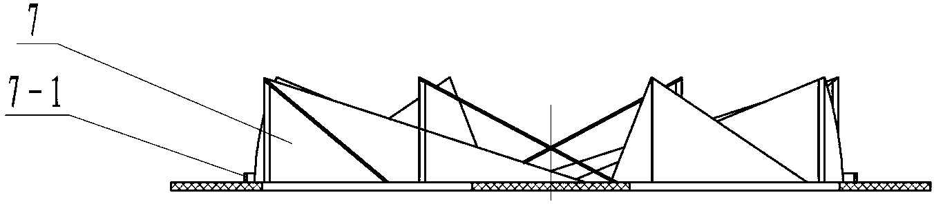
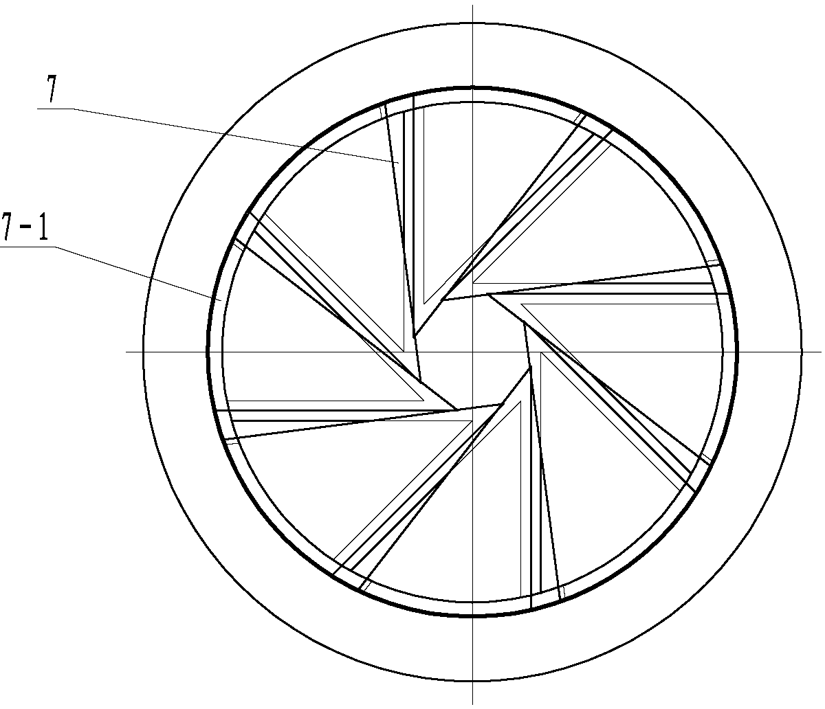
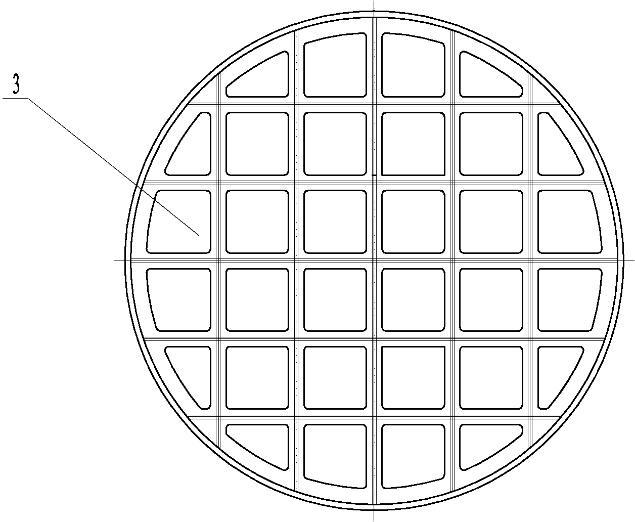
[0022] Such as figure 1 , figure 2 , image 3 As shown, a plastic waste gas washing tower of the present invention comprises a tower body 1, a waste gas inlet 2 arranged at the lower part of the tower body 1, a waste gas exhaust port 9 arranged at the upper part of the tower body 1, and a tower body arranged at the tower body The plate 3, the packing 5 and the spraying device 6 with nozzles are arranged on the observation hole 11 on the side of the tower body. packing, and arranged on the upper part of the column plate 3, on the tower body 1 on the side of the corrugated integral packing, there is a packing port 4, and the uppermost layer of the tower body 1 is provided with a swirl plate 7, and in the swirl The bottom of the flow plate 7 is provided with an annular liquid collection tray 7-1, the side of the tower body is provided with a swirl plate waste liquid outle...


PUM


Abstract

The invention belongs to the technical field of waste gas purification equipment, and in particular relates to a plastic waste gas washing tower. The plastic waste gas washing tower comprises a tower body, a waste gas inlet, a waste gas outlet, more than one tower plate, a filler spraying device and observation holes, and is characterized in that overall corrugated fillers are respectively arranged on the tower plate; a swirl plate is arranged on the top tower plate of the tower body; an annular catch tray is arranged at the lower part of the swirl plate; a swirl plate waste liquid outlet is formed in the side surface of the tower body; a lower tower plate waste liquid outlet is formed in the center at the bottom of the tower body; and the spraying device consists of long spraying pipes with nozzles and short spraying pipes with nozzles, which are uniformly and alternately arranged in the circumferential direction of the tower body. The plastic waste gas washing tower has the advantages of high corrosion resistance, ageing resistance, reasonable structure, stable performance, large processing capacity, small system resistance, convenience for mounting, no maintenance, long service life and the like.

Description

technical field [0001] The invention belongs to the technical field of waste gas purification equipment, in particular to a plastic waste gas washing tower. Background technique [0002] Air pollution and corrosion is a problem that must be solved. In order to solve environmental pollution and air pollution, in the process of industrial waste gas treatment, scrubbers are usually used to deal with pollution factors. The structure of the existing scrubber mainly includes the tower body, which is installed in the tower The exhaust gas inlet at the lower part of the tower body, the exhaust gas outlet at the upper part of the tower body, the tray, packing and spraying device with nozzles arranged in the tower body, the packing of the washing tower generally adopts single-layer bulk Pall ring packing , so some liquid droplets are often entrained by the gas at the outlet of the purified gas, causing secondary pollution and directly affecting the washing effect. It is equipped with...

Claims


Application Information

Patent Timeline
Patent Type & Authority Applications(China)
IPC IPC(8): B01D53/78B01D53/40
Inventor 徐鸿钢杨震郑世义
Owner ALIBEI PLASTIC STORAGE TANK ANSHAN
Why Eureka
Try Eureka