Embedded integrated intelligent die

An embedded and mold technology, applied in the direction of forming tools, manufacturing tools, presses, etc., can solve the problems of speed, acceleration and pressure that cannot be directly obtained, repeated mold adjustments, and inability to fully fit, etc., to reduce mold debugging time and reduce The effect of defective rate, convenient and timely maintenance

Active Publication Date: 2013-08-07
SOHBI CRAFT CHANGSHU
View PDF9 Cites 15 Cited by
  • Summary
  • Abstract
  • Description
  • Claims
  • Application Information

AI Technical Summary

Problems solved by technology

[0003] After long-term practical analysis of the existing molds for the production of stamping parts and sheet metal parts, it is found that the molds in the prior art have the following shortcomings: 1. After the mold is installed on the punching machine, after the closing height adjustment is completed, its height can only be determined by the scale of the punching machine display, but due to the low precision of the punch scale, it is impossible to accurately display the real closed height of the mold. In the secondary production, only by adjusting the height of the punch, the closed height of the mold cannot be adjusted quickly and accurately, and there is a problem of repeated adjustment of the mold
At the same time, due to the differences between different punching machines, the height of the punching machine measured on one punching machine cannot be completely suitable for other punching machines, and there is a problem of repeated adjustment of the mold
2. For the punching times of the mold, it can only be continuously accumulated through the punching times of the punching machine, and the punching times of the mold cannot be quickly and conveniently known
3. For the mold production, the temperature of the mold punch and the die cannot be obtained in time and conveniently
4. The speed, acceleration and pressure suitable for punching products cannot be obtained directly
Chinese patent CN 200610155246.1 discloses an embedded closed-loop control mold protection system. The system installs a sensor on the detected part of the mold, and the signal acquisition device collects the signal sent by the sensor and feeds it back to the control device, thereby realizing the protection of the mold. However, the present invention does not Sensor types and specific functions of undisclosed molds
[0005] In summary, although it is seen in the prior art that the mold is controlled by designing a sensor in the mold, a single sensor is usually set in the mold to control a single variable of the mold. It is common to set a temperature sensor in the mold, but it is not seen in the mold. Displacement sensors, acceleration sensors, pressure sensors, etc. are set in the mold, and there is no comprehensive setting of multiple sensors on the mold to comprehensively control and obtain various experimental parameters in mold production

Method used


Image

  • Embedded integrated intelligent die
  • Embedded integrated intelligent die
  • Embedded integrated intelligent die

Examples


Embodiment 2

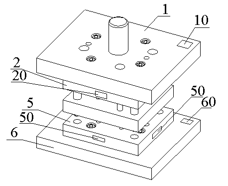
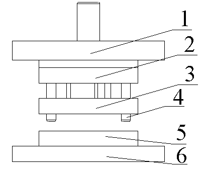
[0034] Embodiment 2: The difference between this embodiment and the above embodiment 1 is that: the die 5 is also provided with a pressure sensor 50 . The pressure sensor 50 adopts a strain gauge pressure sensor, and a strain gauge is provided on the side wall of the die 5 to calculate the pressure on the die during the stamping process by sensing the deformation of the side wall of the die 5, thereby realizing When the mold is reproduced, the data control center automatically adjusts the pressure through the stored data, and at the same time during the processing and production process, the data control center uses the strain gauge to record each pressure in the stamping process to obtain the number of times the mold is used, and then This data is checked against the pre-set mold maintenance frequency to prompt mold maintenance.

Embodiment 3

[0035] Embodiment 3: This embodiment monitors the punching process of the mold in real time. The difference between Embodiment 3 and the above embodiment 2 is that a temperature sensor is embedded in the punch, and the temperature sensor is embedded in the punch and the die. In the vicinity of the contact point, the temperature sensor is used to monitor the real-time temperature of the punch and die during the mold punching process, supervise the mold, and sense the corresponding vulnerable points of the mold. When the actual temperature exceeds a certain theoretical safety value At this time, the stamping operation can be stopped through the data control center, and the position of the vulnerable point of the mold can be prompted and given a warning through display equipment, sound and light alarms, etc.

Embodiment 4

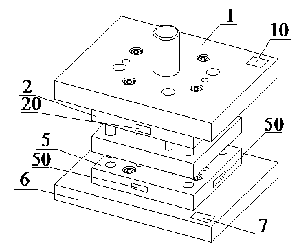
[0036] Embodiment 4: The difference between this embodiment and Embodiment 3 is that a displacement sensor 60 is also provided on the upper end surface of the lower formwork plate 6 . Measure the pressing height of the upper mold base plate 1 during each stamping process by setting a displacement sensor 60 on the upper end surface of the lower mold base plate 6, and transmit the measured data to the data control center for memory storage, so that when When the mold is used on other different punching machines, the punching machine can automatically adjust the stroke through the data stored in the mold, so as to realize the automatic adjustment of the closing height of the mold, so that the adjustment and use of the mold will not be affected by the change of the punching machine, and avoid repeated debugging of the mold. Save costs and greatly improve work efficiency.


PUM


Abstract

The invention discloses an embedded integrated intelligent die which comprises an upper die set plate, an upper die fixing plate, a guide pillar, a core die, a discharging plate, a lower die set plate and a cavity die. The cavity die is arranged on the lower die set plate; the upper die fixing plate is provided with the core die which is matched with the cavity die; the upper die fixing plate is arranged on the upper die set plate; the core die is arranged on the upper die set plate; the guide pillar which penetrates through the discharging plate to be fixed on the upper die set plate enters into the cavity die to guide and correct under the working state of the embedded integrated intelligent die; an elastic device is arranged between the discharging plate and a core die fixing plate; the discharging plate can move up and down along the guide pillar; and the upper die set plate, the cavity die and the lower die set plate are respectively provided with a sensor. Accordingly, the embedded integrated intelligent die has the advantages of being capable of utilizing the sensors which are embedded in the embedded integrated intelligent die to integratedly obtain various information on the embedded integrated intelligent die to adjust technical parameters when the embedded integrated intelligent die works, guaranteeing that die machining is under real-time monitoring and accurate machining conditions, reducing defective products and reducing the rate of the detective products by 20%, improving the working efficiency and being capable of reducing debugging time of the embedded integrated intelligent die by 50%.

Description

technical field [0001] The invention relates to the field of industrial automation control, in particular to an embedded integrated intelligent mold. Background technique [0002] At present, due to the rapid development of my country's modernization construction, the production of various products is increasingly dependent on molds. It is an important tool to improve production efficiency and realize standardized production. Molds are widely used in mass production of today's products. In the prior art, after the mold is installed on the punching machine, various technical parameters of the mold (such as closed height, pressure, temperature, etc.) need to be obtained through the adjustment of the punching machine, etc. Once the conditions of the punching machine change, it is necessary to repeatedly debug the various technologies of the mold At the same time, the statistics of die punching times can only be obtained through the accumulation of punching times of the punchin...

Claims


Application Information

Patent Timeline
Patent Type & Authority Applications(China)
IPC IPC(8): B21D37/10
CPCB30B15/26
Inventor 金垠博管永初葛丽娜杜志刚陆文佳龚志勤
Owner SOHBI CRAFT CHANGSHU
Why Eureka
Try Eureka