Piston assembly capable of achieving flow compensation

A piston assembly and flow compensation technology, applied in the field of hydraulic vibration reduction, can solve problems such as difficult to achieve stepless control, high precision requirements, and poor product consistency, and achieve the effects of convenient manufacture, strong portability, and simple structure

Active Publication Date: 2013-08-07
JILIN UNIV
View PDF6 Cites 2 Cited by
  • Summary
  • Abstract
  • Description
  • Claims
  • Application Information

AI Technical Summary

Problems solved by technology

Traditional flow control valves design multiple different flow areas through mechanical design, and control different flows through switching. The disadvantages are: high machining accuracy requirements and poor product consistency; switching requires the design of auxiliary structures, resulting in complex structures ;Once the design is completed, the flow control cannot be changed, and it is difficult to achieve stepless control

Method used


Image

  • Piston assembly capable of achieving flow compensation
  • Piston assembly capable of achieving flow compensation
  • Piston assembly capable of achieving flow compensation

Examples


Embodiment Construction

[0044] The present invention will be described in detail below in conjunction with the accompanying drawings.

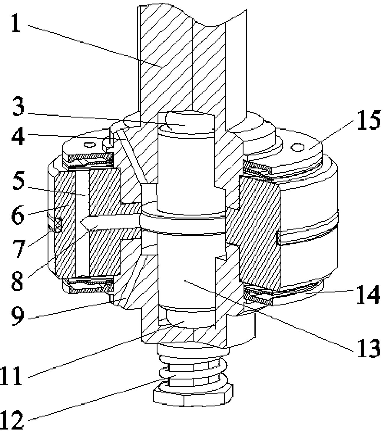
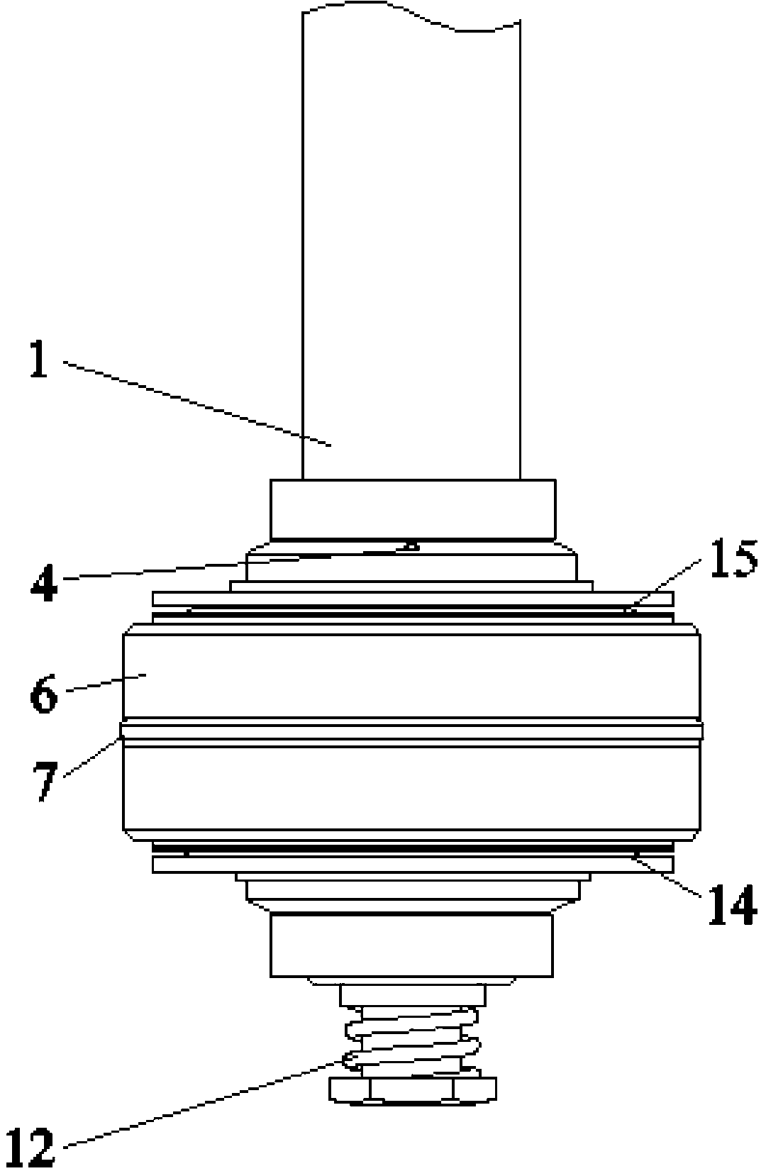
[0045] figure 1 It is an axonometric sectional view of the optimal embodiment of the present invention, showing a piston assembly with flow compensation, including: a piston rod 1, the bottom of which is hollow and disconnected to form an upper rod end 1a and a lower rod end 1b, The hollow interior is slidingly connected with a spool 13;

[0046] The two ends of the spool 13 and the hollow interior of the upper rod end 1a and the lower rod end 1b form two cavities, and the upper elastic chamber 3 and the lower elastic chamber 11 are installed respectively;

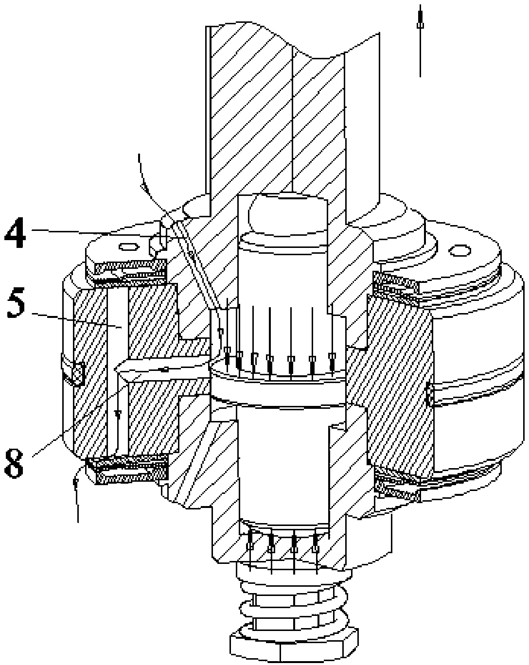
[0047] The outer end surfaces of the upper rod end 1a and the lower rod end 1b are fixed together by the piston 6, and the upper rod end 1a and the lower rod end 1b are respectively provided with an upper auxiliary damping hole 4 and a lower auxiliary damping hole 9, as Figure 6 and Figure 7 As shown, the in...


PUM


Abstract

The invention discloses a piston assembly capable of achieving flow compensation. The piston assembly comprises a piston rod, the bottom of the piston rod is hollow, the piston rod is broken to form an upper rod end and a lower rod end, a valve core is slidingly connected with the hollow inside of the piston rod, two cavities are formed by two ends of the valve core, the hollow inside of the upper rod end and the hollow inside of the lower rod end and are provided with an upper elastic cavity and a lower elastic cavity respectively, the outer end face of the upper rod end and the outer end face of the lower rod end are fixed together through a piston and provided with an upper auxiliary damping hole and a lower auxiliary damping hole respectively, an auxiliary channel which is communicated with damping holes is arranged in the inner circle of the piston, and the ideal speed compensation effect can be obtained through proper selection of the rigidity of the upper elastic cavity and the rigidity of the lower elastic cavity. By the aid of the piston assembly, the moving position of a thrust shaft can be controlled automatically according to the flow of a shock absorber to obtain different flow areas and control flow of oil, besides, electric pneumatic units and drive devices are not required to be added, and the piston assembly is simple in structure, compact, convenient to manufacture, high in transportability and capable of achieving automatic stepless control of bidirectional flow.

Description

technical field [0001] The invention belongs to the technical field of hydraulic damping, and in particular relates to a two-way acting piston assembly with flow compensation which is easy to be modified on the basis of a traditional damper. Background technique [0002] Common flow control valves usually control the flow of fluid by controlling the flow area of ​​the channel. Traditional flow control valves design multiple different flow areas through mechanical design, and control different flows through switching. The disadvantages are: high machining accuracy requirements and poor product consistency; switching requires the design of auxiliary structures, resulting in complex structures ; Once the design is completed, the flow control cannot be changed, and it is difficult to achieve stepless control. With the development of technology, the flow control valve is required to develop in the direction of miniaturization, intelligence and economy. This requires the control ...

Claims


Application Information

Patent Timeline
Patent Type & Authority Applications(China)
IPC IPC(8): F16F9/34F16F9/512
Inventor 章新杰张玉新许男郭孔辉吴雨竹唐帅王众
Owner JILIN UNIV
Why Eureka
Try Eureka