Radial-force-balanced manual control air valve

A balanced, radial force technology, applied to valve details, multi-way valves, valve devices, etc., can solve problems such as inflexible operation, unsafe hidden dangers, and wear of contact surfaces, achieving light and flexible operation, long service life, reliable performance

Active Publication Date: 2013-08-07
阜新北鑫星液压有限公司
View PDF10 Cites 2 Cited by
  • Summary
  • Abstract
  • Description
  • Claims
  • Application Information

AI Technical Summary

Problems solved by technology

During operation, the gas pressure in the air chamber a, the compression and rebound force of the sealing gasket 27 and the compression elastic force of the positioning spring 23 all act on the rotating valve cover 21, and the rotating valve cover 21 transmits the resultant force in the axial direction to the fixedly connected valve. On the baffle plate 22 of the body 25, the end surface of the rotating valve cover 21 and the baffle plate 22 are under the action of this axial force for a long time and rotate and rub against each other, resulting in wear of the contact surface, which increases the friction between the valve body 25 and the rotating valve cover 21. The fit gap between the two end surfaces reduces the compression of the gasket 27, which can easily cause air leakage in the air chamber, resulting in functional damage and unsafe hazards
Due to the presence of axial force, the friction resistance of the rotation of the handle 27 is increased to make the operation inflexible

Method used


Image

  • Radial-force-balanced manual control air valve
  • Radial-force-balanced manual control air valve
  • Radial-force-balanced manual control air valve

Examples


Embodiment Construction

[0014] specific implementation plan

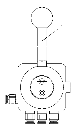
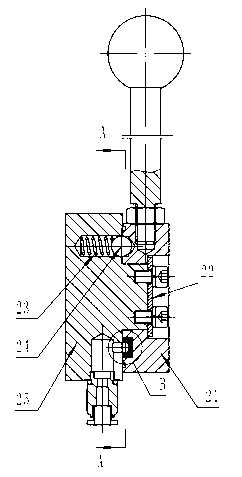
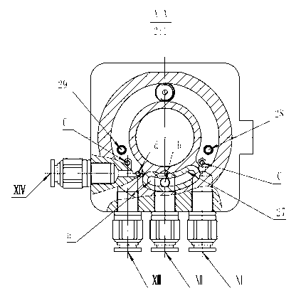
[0015] Refer to attached Figure 5 , 6 , 7, 8, radial force balance manual control air valve, including valve body 1, rotating valve core 2, handle 6, sealing gasket 5, positioning spring 4, steel ball 3 and the first, Ⅱ, Ⅲ, Ⅳ air port joints, which are characterized in that the rotating valve core 2 is placed in the inner hole of the valve body 1 and connected with the handle 6, and the valve body 1 is provided with a groove for the range of rotation of the handle 6, and the handle 6 is connected with the inner hole of the valve body 1. The rotating spool 2 is constrained axially and radially. Turning the handle 6 can make the rotating spool 2 rotate in the inner hole of the valve body 1 according to the stroke range. The steel balls 3 can fall into the positioning grooves C of the valve body 1 respectively. Two sealing pads 5 are symmetrically placed in the outer circular sealing groove of the rotating valve core 2, and the sealing pa...


PUM


Abstract

The invention relates to a radial-force-balanced manual control air valve which is reliable in performance and long in service life. The air valve comprises a valve body, a rotary valve spool, a handle, positioning springs, sealing gaskets and air port joints. The handle is connected with the rotary valve spool to be arranged in an inner hole of the valve body, the handle rotates to enable the rotary valve spool to rotate in the inner hole of the valve body, and steel balls fall into positioning grooves C of the valve body respectively under the action of the positioning springs. The two sealing gaskets are symmetrically arranged in an outer circle sealing groove of the rotary valve spool and form two air chambers A with the wall of the inner hole of the valve body, the two air chambers are communicated through air channels, four air channels are opened on the valve body and communicated with outer channels through the air port joints respectively, and reversing positions are determined according to positioning holes to achieve disconnection or connection between the air chambers and the air port channels. The air valve is free of axial force and effects of radial force, light and flexible to operate, reliable in performance and long in service life.

Description

technical field [0001] The invention belongs to the technical field of pneumatic reversing valves, in particular to a radial force balance manual control air valve in a dump truck pneumatic control system. Background technique [0002] At present, the rotary shaft type manual control air valve structure of the dump truck (as attached figure 1 , 2 , 3, 4), the rotating valve cover 21 is restrained on the cantilever shaft of the valve body 25 by the baffle 22, and the gas enters the sealing gasket 27 on the sealing groove of the rotating valve cover and the valve body 25 through the air inlet joint Ⅻ and the air passage b. In the air chamber a composed of the end face, the rotating valve cover 21 is rotated around the end shaft of the valve body 25 by moving the handle 26, the two limit pins 28, 29 determine the travel range, and the positioning spring 23 supports the steel ball 24 to determine the reversing position. When the air chamber a in the middle position of the hand...

Claims


Application Information

Patent Timeline
Patent Type & Authority Applications(China)
IPC IPC(8): F16K11/02F16K31/60
Inventor 王伟张东超张永利崔洪升
Owner 阜新北鑫星液压有限公司
Why Eureka
Try Eureka