
Online temperature monitoring system for closed cable equipment on basis of wireless radiofrequency technology

A radio frequency and monitoring system technology, applied in thermometers, thermometer parts, measuring devices, etc., can solve the problems of inability to achieve remote information acquisition and timely temperature alarm, inability to conduct real-time temperature monitoring, lack of maturity and wide application, etc. , to achieve the goal of intelligent power grid, solve the lack of temperature monitoring, and facilitate the effect of technological transformation

Inactive Publication Date: 2013-08-07
STATE GRID CORP OF CHINA +1
View PDF3 Cites 13 Cited by
  • Summary
  • Abstract
  • Description
  • Claims
  • Application Information

AI Technical Summary

Problems solved by technology

[0005] 1. Infrared thermal imaging cameras are expensive, inconvenient to carry, and consume a lot of manpower and material resources;
[0006] 2. It is greatly affected by climate and time, and due to the limited number of equipment, the census cannot be realized;
[0007] 3. Only the information at the time of the inspection can be obtained, but the historical temperature information cannot be obtained;
[0008] 4. For the indoor terminal of the cable in the closed position, the temperature information cannot be obtained;
[0009] 5. Real-time temperature monitoring cannot be carried out, and remote information acquisition and timely temperature alarm cannot be realized
Point-type temperature measurement is still at the stage of manual inspection. For temperature measurement with real-time, online and wireless transmission characteristics, there is still a lack of mature and wide-ranging applications.

Method used


Image

  • Online temperature monitoring system for closed cable equipment on basis of wireless radiofrequency technology

Examples


Embodiment

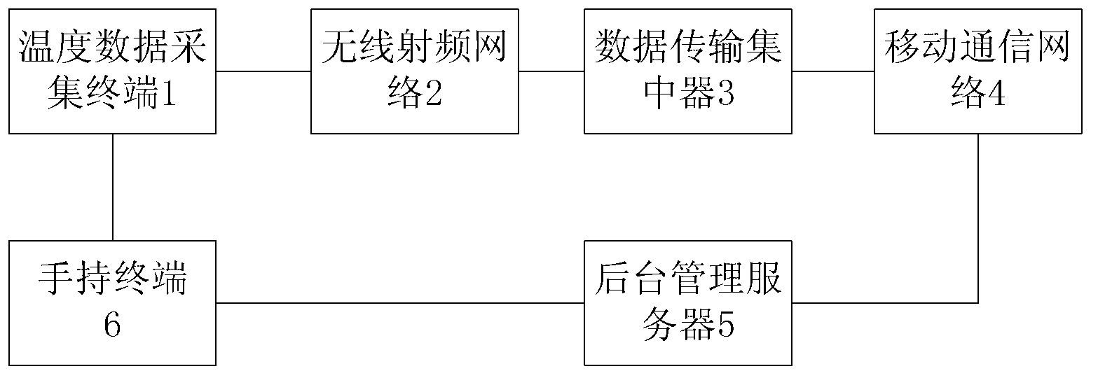
[0030] like figure 1 As shown, a closed cable equipment temperature online monitoring system based on radio frequency technology includes a temperature data collection terminal 1, a radio frequency network 2, a data transmission concentrator 3, a mobile communication network 4, and a background management server 5 connected in sequence;

[0031] After the temperature data collection terminal 1 collects the temperature data, it will be stored locally and judged whether it exceeds the set threshold. If it exceeds, a local alarm will be performed, and the temperature data and alarm information will be sent to the background management server in real time through the data transmission concentrator 3 at the same time. , the background management server saves the received temperature data and alarm information and sends the alarm information to the client, if not exceeded, the temperature data acquisition terminal will send the temperature data to the background management server in ...


PUM


Abstract

The invention relates to an online temperature monitoring system for closed cable equipment on the basis of a wireless radiofrequency technology. The online temperature monitoring system comprises a temperature data acquisition terminal, a wireless radiofrequency network, a data transmission concentrator, a mobile communication network and a back-stage management server which are sequentially connected with one another. After acquiring temperature data, the temperature data acquisition terminal stores the temperature data locally and judges whether the temperature data exceed a set threshold value or not; if the temperature data exceed the set threshold value, the temperature data acquisition terminal gives an alarm locally and transmits the temperature data and alarm information to the back-stage management server via the data transmission concentrator in real time, and the back-stage management server stores the received temperature data and the received alarm information and transmits the alarm information to a client; and if the temperature data do not exceed the set threshold value, the temperature data acquisition terminal transmits the temperature data to the back-stage management server via the data transmission concentrator in real time, and the back-stage management server stores the received temperature data. Compared with the prior art, the online temperature monitoring system has the advantages that damage to the equipment and power failure accidents are effectively prevented, and the like.

Description

technical field [0001] The invention relates to an on-line temperature monitoring system, in particular to an on-line temperature monitoring system for closed cable equipment based on radio frequency technology. Background technique [0002] Online temperature monitoring has been widely used in various fields. For the power industry, real-time online monitoring of the temperature of cables and related equipment is an important measure to ensure the safe and stable operation of the power grid. But so far there is very little work done in this area. [0003] Cable lines are now gradually replacing overhead lines and becoming the main body of urban power grids. Therefore, the network structure is becoming more and more complex, with many joints and branches. These cables are easy to form hot spots one by one at the places where they are connected and tapped. When it is larger, it is easy to overheat and cause damage to the equipment, or even a power failure. Therefore, for th...

Claims


Application Information

Patent Timeline
Patent Type & Authority Applications(China)
IPC IPC(8): G06K7/00G01K1/02G01K13/00
Inventor 蒋晓娟王媚闵红钱天宇吴成建
Owner STATE GRID CORP OF CHINA
Learn More