Pneumatic performance testing method as well as pneumatic performance testing device

A technology of aerodynamic performance and test methods, which is used in aerodynamic tests, measurement devices, engine tests, etc.

Active Publication Date: 2013-08-07
CHINA AVIATION POWER MACHINE INST
View PDF5 Cites 17 Cited by
  • Summary
  • Abstract
  • Description
  • Claims
  • Application Information

AI Technical Summary

Problems solved by technology

[0004] The purpose of the present invention is to provide an aerodynamic performance test method and test device for particle separators to solve the technical problems of testing the aerodynamic performance of particle separators

Method used


Image

  • Pneumatic performance testing method as well as pneumatic performance testing device
  • Pneumatic performance testing method as well as pneumatic performance testing device
  • Pneumatic performance testing method as well as pneumatic performance testing device

Examples


Embodiment Construction

[0042] The embodiments of the present invention will be described in detail below with reference to the accompanying drawings, but the present invention can be implemented in many different ways defined and covered by the claims.

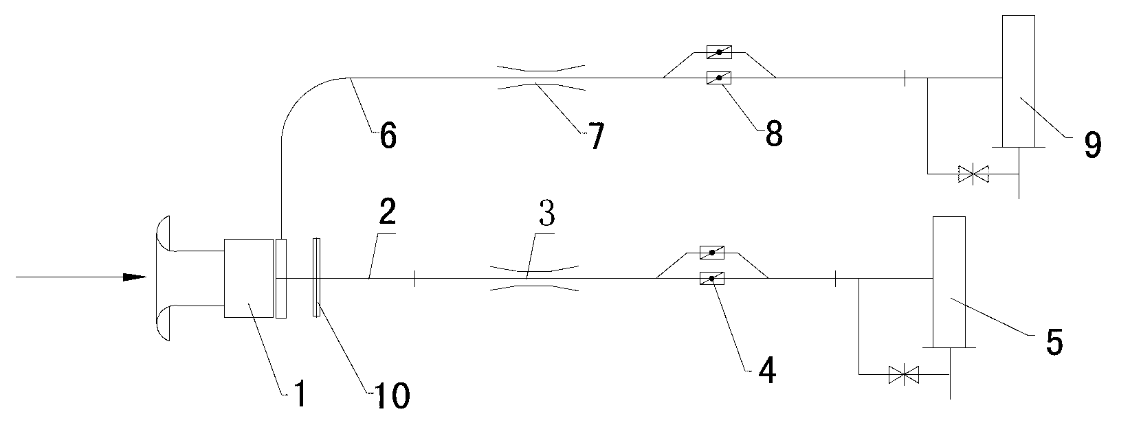
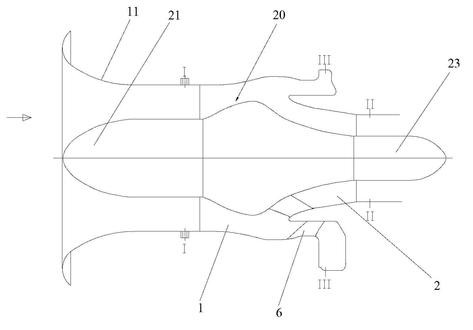
[0043] refer to Figure 1 to Figure 2 , the present invention provides a kind of aerodynamic performance testing device, is suitable for the aerodynamic performance test of particle separator, and this aerodynamic performance testing device comprises: inlet channel 1, main air flow channel 2 and cleaning flow channel 6; main air flow channel 2 and scavenging flow channel 6 are connected to the intake channel 1, along the figure 1 , figure 2 The air flowing into the inlet channel 1 in the direction indicated by the middle arrow passes through the main air flow channel 2 and the purge flow channel 6 and flows out in two ways. In this example, refer to figure 2 , the inner hollow fairing 11 is provided with a cone 20 inside, the axial direction of...


PUM


Abstract

The invention discloses a pneumatic performance testing method as well as a pneumatic performance testing device. The method comprises the following steps of: simulating and generating a primary air stream and a scavenging stream in a primary air stream flow passage and a scavenging stream flow passage of a particle separator; measuring the total pressure value Pt1 of an inlet cross section of an air intake duct of the particle separator; then regulating the primary air stream outlet flow rate Q1 and the scavenging stream outlet flow rate Q2 of the particle separator respectively so as to enable the SCR to correspond to the preset value, wherein the SCR is equal to Q2 / Q1; measuring the outlet cross section total pressure value Pt2 in the primary air stream flow passage of the particle separator; and calculating the air intake total pressure loss value delta P. The device comprises the air intake duct, the primary air stream flow passage and the scavenging stream flow passage as well as air pumping fans arranged on the flow passages as well as a pressure measuring unit, a flow rate measuring unit and a flow rate regulating unit. The method and the device provided by the invention provide a quantization means for evaluating performances of the particle separator, and whether the performances of the particle separator correspond to the whole machine performance index of an engine can be tested conveniently.

Description

technical field [0001] The invention relates to the field of turboshaft engines, in particular to an aerodynamic performance testing method and testing device for particle separators of turboshaft engines. Background technique [0002] The integral particle separator is a unique air intake device for turboshaft engines. The flow channel of the particle separator is divided into main air flow and purge flow. The main function of the particle separator is to intake air and remove foreign objects (such as sand, leaves, grass, birds, etc.) Inertial force field to achieve the purpose of separating foreign objects. [0003] The performance of the particle separator directly affects the service life of the turboshaft engine. Therefore, it is necessary to conduct a total pressure loss test of the intake flow path for the particle separator of the turboshaft engine to verify whether the performance index of the particle separator meets the design requirements. . Contents of the i...

Claims


Application Information

Patent Timeline
Patent Type & Authority Applications(China)
IPC IPC(8): G01M9/06G01M15/00
Inventor 陈冰冯为刘龙初
Owner CHINA AVIATION POWER MACHINE INST
Why Eureka
Try Eureka