Lip seal test experiment table

A test experiment, lip sealing technology, applied in the testing of mechanical parts, the testing of machine/structural parts, measuring devices, etc., can solve the problem of inability to reflect the leak-proof ability of sealing components, inability to judge the quality of processing and assembly of sealing components, and poor machinery and equipment. impact, etc.

Active Publication Date: 2012-10-03
TSINGHUA UNIV +1
View PDF4 Cites 8 Cited by
  • Summary
  • Abstract
  • Description
  • Claims
  • Application Information

AI Technical Summary

Problems solved by technology

[0003] At present, there is still a lack of effective technical means for testing the performance of lip seals. There are two commonly used methods: one is to use a general friction and wear testing machine to conduct tribological tests on sealing materials, mainly to test the friction coefficient of materials. , wear resistance and other tribological properties are far from the actual use of the sealing element, so this test method cannot reflect the leakage prevention ability of the sealing element under actual working conditions, nor can it judge the processing and assembly quality of the sealing element; therefore, If the sealing ring is applied to the actual working system only based on the results obtained from this test, it is likely to cause serious adverse effects on the machinery and equipment; the other is to use bench experiments to simulate actual working conditions and measure Leakage
However, the leakage is only one of the comprehensive performance indicators of the sealing ring, so this experimental method cannot comprehensively evaluate the performance of the sealing ring

Method used


Image

  • Lip seal test experiment table
  • Lip seal test experiment table
  • Lip seal test experiment table

Examples


Embodiment Construction

[0013] The present invention will be described in further detail below in conjunction with the accompanying drawings and embodiments.

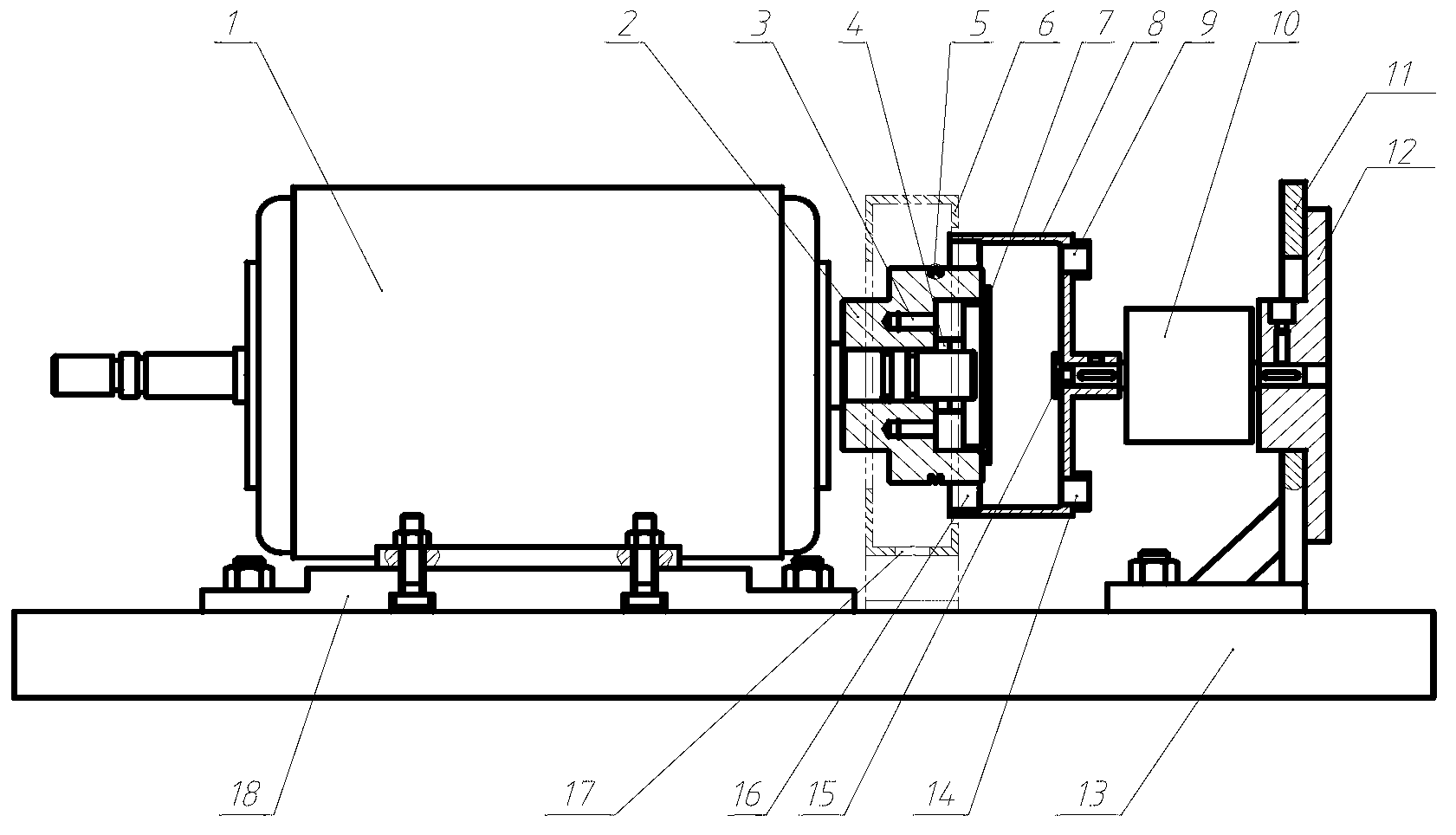
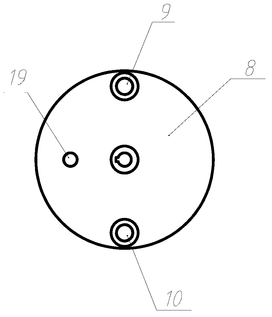
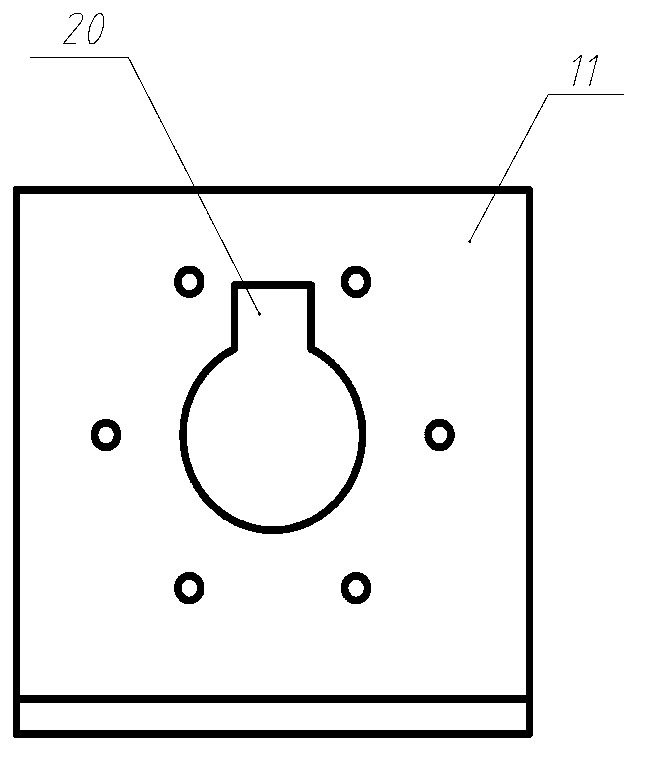
[0014] Refer to attached figure 1 , a lip seal test bench, including a T-slot platform 13, one end of the T-slot platform 13 is provided with a flange support 11, and the other end is equipped with a motor base 18, in order to avoid other parts and flange supports 11, there is a groove 20 on the flange support. An AC motor 1 and an external frequency converter are installed on the motor base 18 to realize stepless speed regulation. The hole 3 is equipped with an oil chamber 8, the oil chamber 8 is keyed to the static torque sensor 10, the right end of the static torque sensor 10 is loaded into the connecting flange 12 through a key connection, and the right end of the connecting flange 12 is fixed to the flange support 11 by bolts ; The shaft sleeve 2 is sleeved with an oil convex point 5, the right side of the shaft sleeve 2 is equipped wit...


PUM


Abstract

The invention relates to a lip seal test experiment table, which comprises a T-shaped groove platform, wherein the T-shaped groove platform is provided with an alternating-current motor, and the alternating-current motor is fixedly provided with a shaft sleeve. An oil chamber is installed on the shaft sleeve and is connected with a static torque sensor through a key, and the right end of the static torque sensor is put into a connecting flange through key connection. An oil spur is sheathed onto the shaft sleeve, and the right side of the shaft sleeve is provided with a plastic end cover. An oil limiting chamber is fixedly arranged on the T-shaped groove platform through bolt connection, and the bottom of the oil limiting chamber is provided with an oil leak hole. A lip-shaped seal ring is installed into the oil chamber. The lip seal test experiment table can inspect the function of the lip-shaped seal ring and the feasibility and the reliability of key components under simulation of the actual condition, and a seal performance test of the seal ring under the working condition is realized. A research for expanding the test range of the inner diameter of the seal ring is realized, and a research of the disassembly process and method of the shaft sleeve is realized. A research of the influence of temperature on the seal effect is realized, and the lip seal test experiment table mainly measures the temperature change in a contact area of the shaft sleeve and the seal ring and an oil supply chamber. The lip seal test experiment table can conduct experiments to a plurality of tested seal rings at the same time.

Description

technical field [0001] The invention relates to a test bench for testing the comprehensive performance of sealing elements, in particular to a lip seal test bench. Background technique [0002] Whether the mechanical equipment can operate normally and whether the performance can be performed well is closely related to the design of the sealing structure and the sealing performance of the sealing element. If the seal fails, the loss caused by the leakage of the working medium or lubricating fluid is very alarming, which not only increases the friction, wear and power consumption of the machine, shortens the working life of the machine, but also causes environmental pollution and corrosion of equipment due to leakage. and working environment. More serious also can catch fire and explode because of this, cause the safety accident of personal, equipment. Therefore, carrying out research on sealing technology has become one of the key research projects in the current technical ...

Claims


Application Information

Patent Timeline
Patent Type & Authority Applications(China)
IPC IPC(8): G01M13/00
Inventor 郭飞贾晓红高志黄乐索双富王玉明
Owner TSINGHUA UNIV
Why Eureka
Try Eureka