
Photoelectric-separated intelligent optical fiber connector

A technology of active connectors and electrical connectors, applied in the coupling of optical waveguides, bases/housings, etc., can solve problems such as increased research and development costs, performance is easily affected by the environment, and volume and cost are difficult to reduce, so as to improve product quality and The effect of producing batches, solving intelligent management problems, and reducing production and stocking varieties

Active Publication Date: 2015-03-11
JIANGSU HENGTONG PHOTOELECTRIC +1
View PDF5 Cites 0 Cited by
  • Summary
  • Abstract
  • Description
  • Claims
  • Application Information

AI Technical Summary

Problems solved by technology

Although RFID technology can obtain the advantage of no wiring at the connection port, since the RFID card reader always works in a resonant analog working state, this causes problems such as high power consumption of the circuit, and the performance is easily affected by the environment and fluctuates. The unavoidable coil makes it difficult to reduce the size and cost, so the contact electronic tag technology is still popular for its unique performance
[0003] Since smart ODN is still in the early stage of technological development, and FTTH construction is highly sensitive to cost, smart ODN equipment using contact electronic label technology must be connected and adapted to optoelectronics. There are very few companies, so the design and processing of contact photoelectric connectors and the high cost have become a major obstacle to the development of smart ODN. In addition, there are many types of optical fiber active connectors, and redesigning various types of photoelectric integrated contacts Type intelligent optical fiber active connector will not only increase R&D costs, but also dilute the overall demand for each device, which is not conducive to cost reduction, and the optoelectronic integrated design will also cause the need for overall replacement due to a connector failure, which also makes It is difficult to implement the intelligent transformation of the existing network wiring equipment

Method used


Image

  • Photoelectric-separated intelligent optical fiber connector
  • Photoelectric-separated intelligent optical fiber connector
  • Photoelectric-separated intelligent optical fiber connector

Examples


Embodiment 1——4

[0028] Example 1-SC type photoelectric separation smart optical fiber active connector indicated by the light guide posts on both sides of the 4-wire slot:

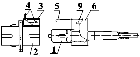
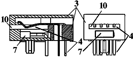
[0029] Such as figure 2 As shown, an electrical connector plug 5 with four golden finger electrical contact points 8 and a contact type electronic label storage chip 9 is fixed on the plug interconnection fixing body 6 through the mounting and fixing slot 11, and is clamped on the SC-type optical fiber movable connector On the movable cover of the plug 1, the gold finger contact point 8 of the electrical connector plug faces the SC-type optical fiber movable connector plug 1, and the exposed electrostatic protection ground 12 is laid on the periphery of the component side of the electrical connector plug 5, and the reverse side is laid bare The ground plane protection layer constitutes a smart optical fiber movable connector plug; four electrical connector elastic contact pins 4 are installed in the independent electrical co...

Embodiment 2

[0030] Example 2-LC type photoelectric separation smart optical fiber active connector indicated by the light guide posts on both sides of the 2-wire slot:

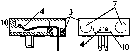
[0031] Such as image 3 As shown, the electrical connector plug 5 with two golden finger electrical contact points 8 and a contact type electronic label storage chip 9 is fixed on the plug interconnection fixing body 6 through the mounting and fixing groove 11, and is clamped on the LC type optical fiber movable connector On the movable cover of the plug 1, the gold finger contact point 8 of the electrical connector plug faces the LC-type optical fiber movable connector plug 1, and the exposed electrostatic protective ground 12 is laid on the periphery of the component side of the electrical connector plug 5, and the reverse side is laid bare The ground plane protection layer constitutes a smart optical fiber movable connector plug; two electrical connector elastic contact pins 4 are installed in the independent electrical co...

Embodiment 3

[0032] Example 3-MPO type photoelectric separation smart optical fiber active connector indicated by the LED beside the 3-wire slot:

[0033] Such as Figure 4 As shown, the electrical connector plug 5 with three golden finger electrical contact points 8 and a contact type electronic label storage chip 9 is fixed on the plug interconnection fixing body 6 through the mounting fixing groove 11, and is clamped on the MPO type optical fiber movable connector On the movable cover of the plug 1, the gold finger contact point 8 of the electrical connector plug faces the MPO-type optical fiber movable connector plug 1, and the exposed electrostatic protection ground 12 is laid on the periphery of the component side of the electrical connector plug 5, and the reverse side is laid bare The ground plane protection layer constitutes the intelligent optical fiber movable connector plug; the independent electrical connector socket body 3 is equipped with an electrical connector elastic contact ...


PUM


Abstract

The invention relates to a photoelectric-separated intelligent optical fiber connector which comprises a optical fiber connector plug, an electric connector plug, an electric connector elastic contact needle, a light emitting indicator and a contact type electronic tag storage chip. The optical fiber connector plug is used for being inserted into the optical fiber connector. The electric connector plug is used for being inserted in a slot of an electric connector socket while the optical fiber connector plug is inserted into the optical fiber connector. The electric connector elastic contact needle used for maintaining good contact with gold finger on the electric connector plug, and the other end of the electric connector elastic contact needle extends out of the electric connector socket to be conveniently connected with an intelligent optical distribution device circuit. The light emitting indicator is mounted on one side of the slot. Corresponding pins of the contact type electronic tag storage chip are used for being electrically connected to corresponding electric contacts of the gold finger. The optical fiber connector plug and the electric connector plug are fixedly integrated through a plug connecting fixing body.

Description

Technical field [0001] The invention relates to the technical field of optical communication intelligent wiring, in particular to a photoelectrically separated intelligent optical fiber movable connector. Background technique [0002] With the development of technology, xDSL has been unable to meet users' broadband access requirements. The rapid maturity of FTTH and cost reduction have brought a new round of broadband communication construction climax, and the global ODN (Optical Distribution Network) ushered in explosive growth. Since FTTH mainly uses PON (passive optical network) technology, it splits an OLT (optical line terminal) to dozens or hundreds of ONUs (optical network units), which makes the user end of the ODN network produce a large number of optical fibers The wiring needs to be scheduled for maintenance and management. For this kind of point-to-multipoint (P2MP) line, if we continue to use character labels that can only be manually identified for fiber wiring man...

Claims


Application Information

Patent Timeline
Patent Type & Authority Patents(China)
IPC IPC(8): G02B6/38H01R13/46
Inventor 钱建林王英明孙权易云志杨夏芬
Owner JIANGSU HENGTONG PHOTOELECTRIC
Learn More