Method for optimizing key parameters of bearingless permanent magnet motor

A technology of permanent magnet motor and key parameters, applied in synchronous machine parts, manufacturing stator/rotor body, etc., can solve the problems of increasing the difficulty and complexity of motor design, achieve short design and development time, clear design ideas, easy to use The effect of engineering

Inactive Publication Date: 2013-08-07
JIANGSU UNIV
View PDF0 Cites 7 Cited by
  • Summary
  • Abstract
  • Description
  • Claims
  • Application Information

AI Technical Summary

Problems solved by technology

Since the permanent magnet magnetic field, the magnetic field generated by the torque winding current and the magnetic field generated by the levitation winding current exist in the bearingless permanent magnet motor, and the output torque and levitation force of the motor are generated in the same air gap magnetic field, the design of the prototype must be considered at the same time The two indicators of output torque and suspension force increase the difficulty and complexity of motor design
Therefore, the traditional design method of the permanent magnet motor body is not suitable for the design of the bearingless permanent magnet motor. Able to design a bearingless permanent magnet motor that meets the performance requirements under the conditions

Method used


Image

  • Method for optimizing key parameters of bearingless permanent magnet motor
  • Method for optimizing key parameters of bearingless permanent magnet motor
  • Method for optimizing key parameters of bearingless permanent magnet motor

Examples


Embodiment Construction

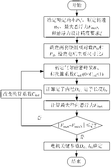
[0015] as the picture shows, figure 1 It is a flow chart of the key parameter optimization design method of the bearingless permanent magnet motor taking into account both the suspension force and the torque, and the figure specifically describes various details in the optimization design process. The specific implementation steps are as follows:

[0016] Step 1: Determine the rated power P of the bearingless permanent magnet motor according to the design requirements N ', rated speed n N , the required maximum suspension force F maxN And the maximum suspension force design accuracy requirements ξ.

[0017] Step 2: Select the number of pole pairs of the two sets of windings of the bearingless permanent magnet motor, that is, the number of pole pairs of the torque winding P M , and the number of pole pairs of the suspension winding is P B , and satisfy P B =P M ±1; select the main size ratio λ of the bearingless permanent magnet motor.

[0018] Step 3: Preliminary selec...


PUM


Abstract

The invention discloses a method for optimizing key parameters of a bearingless permanent magnet motor considering both suspension force and torque. The method comprises the following steps that 1, the design parameters of the bearingless permanent magnet motor are selected according to design requirements; 2, the suspension winding pole-pair number PB and the torque winding pole-pair number PM of the bearingless permanent magnet motor are determined, and in addition, PB is equal to PM+/-1; 3, the calculated value of the maximum suspension force is obtained by a finite element method; 4, the calculated value Fmax of the maximum suspension force obtained in the step 3 is compared with the suspension force design requirement value FmaxN, when the calculated value does not conform to the design requirement, namely the absolute value of the difference value of Fmax and FmaxN is greater than Xi, Xi is the design precision requirement of the maximum suspension force, the conversion coefficient Cred (Cred is greater than 0 but is smaller than 1) is increased or decreased, then, the repeated iteration is carried out until the calculated value Fmax of the maximum suspension force conforms to the design precision requirement, finally, the optimized key parameters of the bearingless permanent magnet motor, including the stator inner diameter Dsi and the stator length IFe are obtained. The method has the advantages that the design thought is clear, the design and development time is short, the operation is simple, and the like.

Description

technical field [0001] The invention belongs to the design field of electromechanical energy conversion devices, in particular to a method for designing key structural parameters of a bearingless permanent magnet motor. Background technique [0002] As far as the structure is concerned, the bearingless permanent magnet motor only has one more set of suspension windings on the stator than the traditional permanent magnet motor. The main body size calculation formula of the motor is used in the body design of the bearingless permanent magnet motor, and the follow-up design is carried out on this basis. This design often sacrifices the torque for the levitation force performance, so it cannot satisfy both levitation force and Torque performance requirements. At present, a relatively systematic, practical and generally recognized design method has not been established. Since the permanent magnet magnetic field, the magnetic field generated by the torque winding current and the...

Claims


Application Information

Patent Timeline
Patent Type & Authority Applications(China)
IPC IPC(8): H02K21/02H02K15/02
Inventor 孙晓东陈龙江浩斌杨泽斌李可
Owner JIANGSU UNIV
Why Eureka
Try Eureka