Dynamic kinematic acquisition system for human body bone joint

An acquisition system and bone joint technology, applied in medical science, radiological diagnosis equipment, diagnosis, etc., can solve problems such as single function, complicated operation, and lack of targeted data interface

Inactive Publication Date: 2013-08-14
THE FIRST AFFILIATED HOSPITAL OF THIRD MILITARY MEDICAL UNIVERSITY OF PLA
View PDF5 Cites 13 Cited by
  • Summary
  • Abstract
  • Description
  • Claims
  • Application Information

AI Technical Summary

Problems solved by technology

The installation and use of this kind of self-built system is extremely cumbersome, and has a single function and poor stability
Multiple physical parameters required for post-processing, such as focal length, focal-object distance, projection angle, etc., all need to be manually measured and recorded, and matched with X-ray images, which cannot be automatically acquired and integrated
At the same time, due to the lack of targeted data interface, X-ray images and physical parameters in the post-processing need to be manually input, and cannot be performed automatically
In addition, the installed system can only be adapted to specific tests. For subjects of different heights, different body parts and different forms of movement, it needs to be reinstalled and calibrated, and cannot be adjusted flexibly
In short, the self-built system is still experimental in nature, its operation is complicated, its stability is poor, its accuracy is low, its detection is time-consuming, and its cost is high, so it is not suitable for clinical application.

Method used


Image

  • Dynamic kinematic acquisition system for human body bone joint
  • Dynamic kinematic acquisition system for human body bone joint
  • Dynamic kinematic acquisition system for human body bone joint

Examples


Embodiment Construction

[0026] The preferred embodiments of the present invention will be described in detail below in conjunction with the accompanying drawings; it should be understood that the preferred embodiments are only for illustrating the present invention, rather than limiting the protection scope of the present invention.

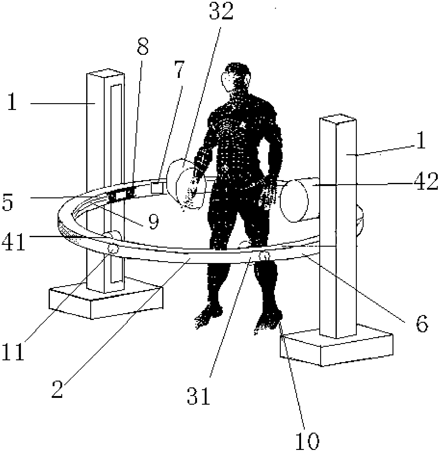
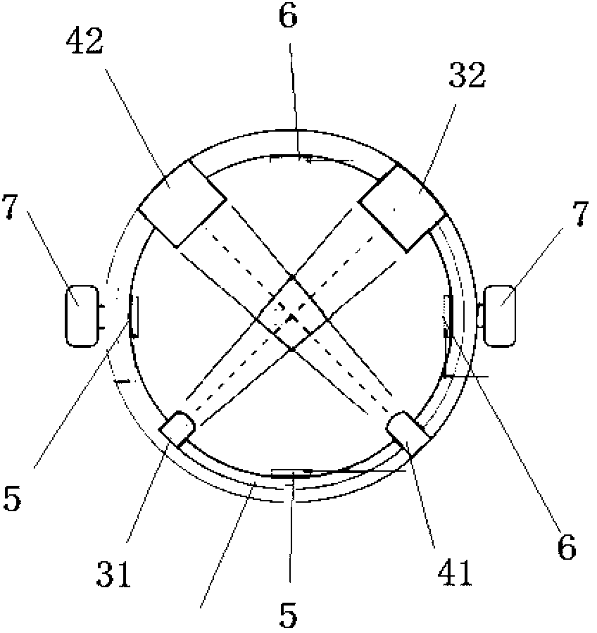
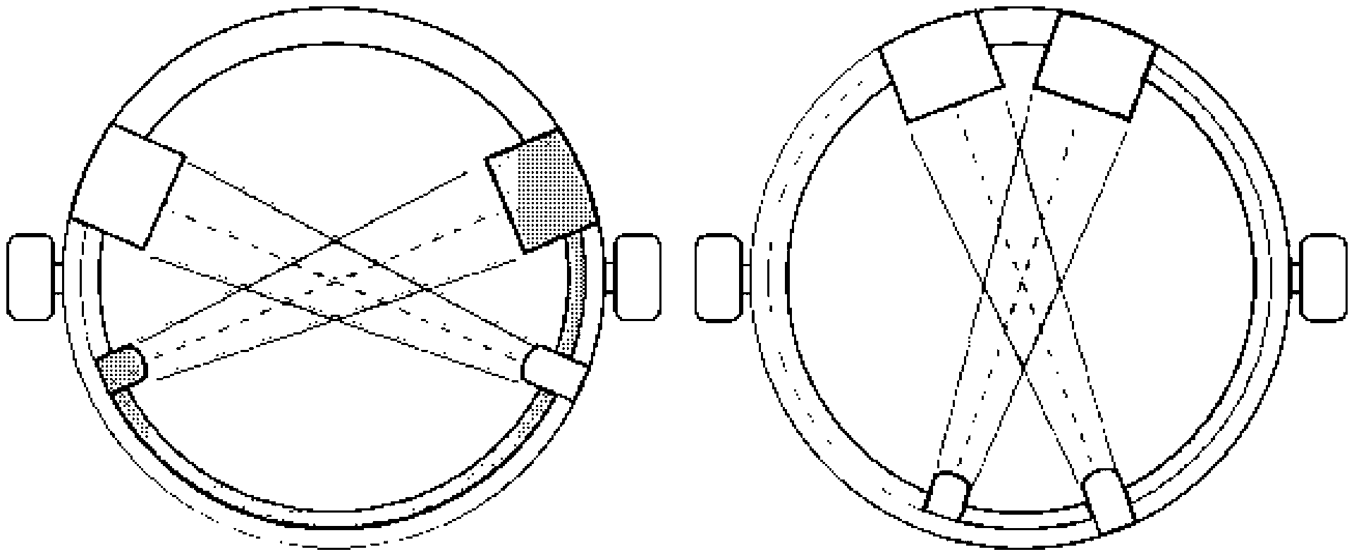
[0027] figure 1 is the overall perspective view of the device, figure 2 is the plan view of the circular slide rail, image 3 For the adjustment of the projection angle and the detection area, in the figure, the overlapping area of ​​the two sets of X-rays is the detection area, and the range of the detection area can be changed with the change of the projection angle. Figure 4 It is a schematic diagram of later data processing (3D model-2D image registration), Figure 5 It is an overall structural diagram, as shown in the figure: the dynamic acquisition system of human bone joint kinematics provided by the present invention includes a first support 1 and a second s...


PUM


Abstract

The invention discloses a dynamic kinematic acquisition system for a human body bone joint. The system comprises first brackets and a second bracket which are movably connected, and a data storage device recording position data of a first plane X-ray dynamic acquisition device and a second plane X-ray dynamic acquisition device, wherein a first X-ray bulb tube and a second X-ray bulb tube used for emitting X-rays, X-ray receivers and a plurality of motional somatosensory camera shooting devices used for capturing body surface motion and position information of the targeted bone joint are arranged on the second bracket at intervals; the two X-ray bulb tubes and the X-ray receiver group can slip on an annular arm of the second bracket in a linkage manner, so that an angle between the two projection X-rays is adjusted, and the shape and the size of a detecting area are adjusted; and with the assistance of the body surface motion information of a targeted limb, in-vivo motion of the bone joint is reconstructed through registration between a pre-established three-dimensional model of the bone joint and an acquired bi-plane two-dimensional image. The system is simple in structure and low in cost, and can acquire an in-vivo motion image of the human body bone joint accurately and quickly.

Description

technical field [0001] The invention relates to the field of medical equipment, in particular to a dynamic acquisition system for human bone joint kinematics. Background technique [0002] The occurrence and development of bone and joint injuries and diseases are often accompanied by changes in local joint motion characteristics. At the same time, some abnormal joint activities can also lead to diseases. Detecting the kinematic characteristics of the bone and joint system in vivo is of great significance to the scientific research, diagnosis, treatment and prognosis evaluation of diseases. [0003] Optical motion capture and motion sensing are currently widely used kinematic detection methods. However, in these methods, optical markers or physical sensors that capture motion are installed on the surface of the limbs. Due to the large relative movement between the skin and bony structures, the limb movement information obtained by the above methods is not suitable for accur...

Claims


Application Information

Patent Timeline
Patent Type & Authority Applications(China)
IPC IPC(8): A61B6/00
CPCA61B6/4014
Inventor 尹力陈凯宁杨柳
Owner THE FIRST AFFILIATED HOSPITAL OF THIRD MILITARY MEDICAL UNIVERSITY OF PLA
Why Eureka
Try Eureka