Tightly-coupled exhaust manifold assembly

An exhaust manifold, tightly coupled technology, used in exhaust devices, mufflers, engine components, etc., can solve problems affecting mass production speed, difficulty, and increasing the number of engine parts

Inactive Publication Date: 2013-08-14
SAIC-GM-WULING AUTOMOBILE CO LTD
View PDF7 Cites 4 Cited by
  • Summary
  • Abstract
  • Description
  • Claims
  • Application Information

AI Technical Summary

Problems solved by technology

This not only increases the number of parts of the engine and increases the production cost of

Method used


Image

  • Tightly-coupled exhaust manifold assembly
  • Tightly-coupled exhaust manifold assembly
  • Tightly-coupled exhaust manifold assembly

Examples


Embodiment Construction

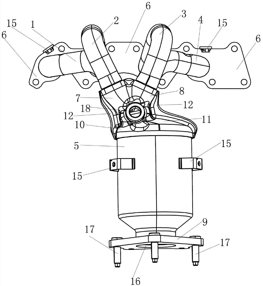
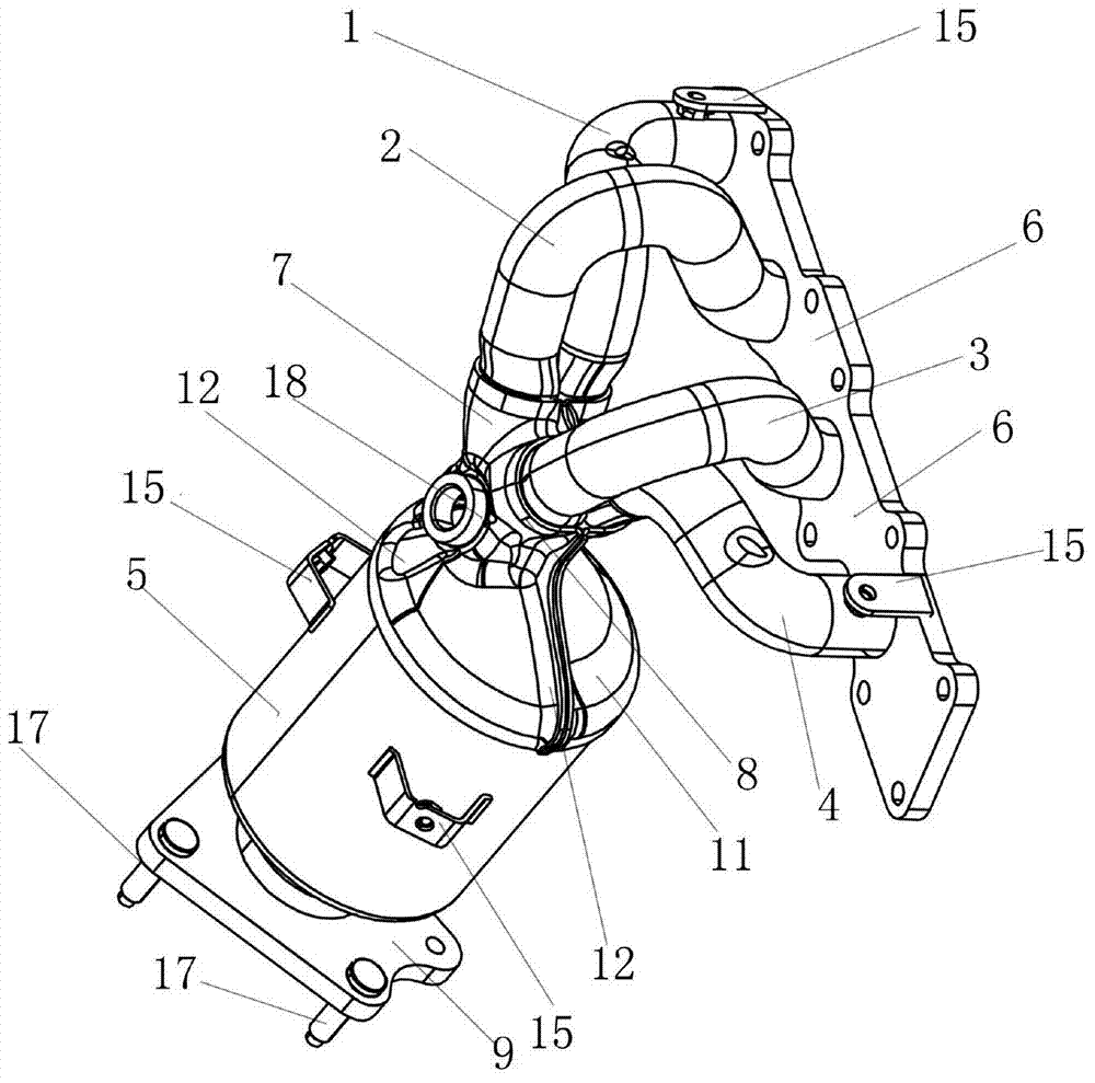
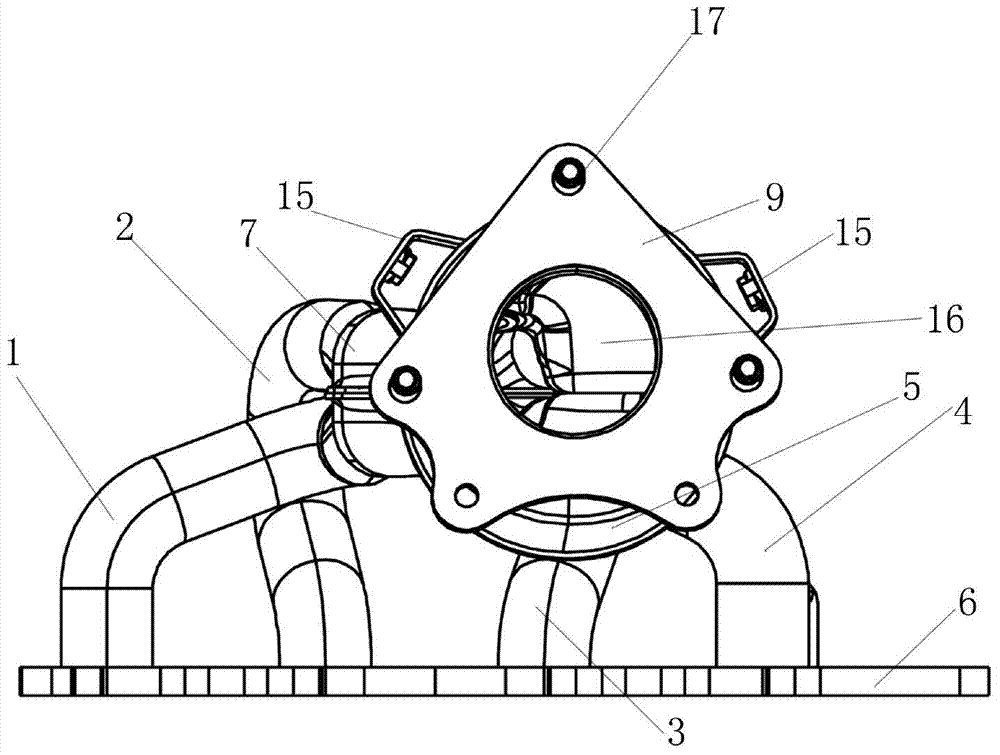
[0025] The following with attached Figure 1 to Figure 6 A close-coupled exhaust manifold assembly of the present invention is further described in detail.

[0026] A close-coupled exhaust manifold assembly of the present invention, please refer to Figure 1 to Figure 6 , including an exhaust manifold assembly and a three-way catalytic converter 5 that is conductively coupled to the exhaust manifold assembly, and the three-way catalytic converter 5 is connected to the exhaust manifold assembly through clam shells, so The exhaust manifold assembly includes a first manifold 1, a second manifold 2, a third manifold 3 and a fourth manifold 4, which are installed on the intake flange 6 at the front end and arranged in sequence from one side to the other. The ends of the first manifold 1 and the second manifold 2 extend into the front end of the first converging pipe 7, and the ends of the third manifold 3 and the fourth manifold 4 extend into the front end of the second converging...


PUM


Abstract

The invention discloses a tightly-coupled exhaust manifold assembly which comprises an exhaust manifold component and a three-way catalytic converter conducted and coupled with the exhaust manifold component. The three-way catalytic converter and the exhaust manifold component are connected through a clamshell. The exhaust manifold component comprises a first manifold, a second manifold, a third manifold and a third manifold with front ends mounted on an air inlet flange and arranged from one side to the other side sequentially. The tail ends of the first and second manifolds extend into the front end of a first convergence pipeline, the tails of the third and fourth manifolds extend into the front end of a second convergence pipeline, the tail ends of the first and second convergence pipelines extend into the clamshell, the tail end of the clamshell is connected with the three-way catalytic converter, and the bottom of the three-way catalytic converter is connected with the air inlet flange. The tightly-coupled exhaust manifold assembly is simple in structure and light in weight, number of parts is reduced, oil consumption and production cost are lowered, the temperature of the three-way catalytic converter is increased, airflow interference is avoided and engine performance is improved.

Description

technical field [0001] The invention relates to a manifold assembly, in particular to a tightly coupled exhaust manifold assembly. Background technique [0002] At present, the volume of the engine is constantly shrinking, and the power per liter is increasing, which leads to the continuous rise of the exhaust temperature of the engine. Therefore, the heat resistance of the exhaust manifold of the engine is getting higher and higher, and must Avoid thermal stress concentration in structural design and meet the requirements of strength and durability. At present, the exhaust manifold of many engines is made of cast iron, which is separated from the three-way catalytic converter. The exhaust manifold and the three-way catalytic converter are connected by bolts and flanges. The number of parts connected in the middle is more and more expensive. . The cast iron exhaust manifold has a large mass, which increases the overall weight of the vehicle; and the large heat capacity is ...

Claims


Application Information

Patent Timeline
IPC IPC(8): F01N13/10
Inventor 林丽安莫江红杨文贞
Owner SAIC-GM-WULING AUTOMOBILE CO LTD
Why Eureka
Try Eureka