Split crank shaft structure of reciprocating compressor

A compressor and reciprocating technology, applied in the direction of the crankshaft, etc., can solve the problems of increasing parts inventory, increasing piston wear and power consumption, and difficult to guarantee precision precision, so as to improve productivity, save processing costs, and maintain structural integrity. Effect

Inactive Publication Date: 2013-08-14
WANBAO GROUP COMPRESSOR CO LTD
View PDF10 Cites 10 Cited by
  • Summary
  • Abstract
  • Description
  • Claims
  • Application Information

AI Technical Summary

Problems solved by technology

[0003] The connecting structure of existing reciprocating compressor cylinder block, crankshaft and connecting rod includes the following several, prior art as figure 1 As shown, the cylinder block 4, the crankshaft 3 and the connecting rod 5 are all integrated. The compressor of this structure is provided with an avoidance groove 41 on the cylinder block 4. During installation, the connecting rod 5 passes through the avoidance groove 41 to move the crankshaft 3 and the piston. Connected together, the setting of the avoidance groove 41 facilitates the installation of the connecting rod 5, but affects the structural integrity of the cylinder block 4 and increases the processing cost of the cylinder block 4; at the same time, during the honing process of the cylinder block 4, due to the honing rod Uneven stress reduces the verticality accuracy of the 4-axis hole and the cylinder hole of the cylinder block, which increases piston wear and power consumption during the operation of the compressor, reducing the efficiency and reliability of the compressor
Existing technologies such as figure 2 As shown, the cylinder block 4 and the crankshaft 3 are integrated, and the connecting rod 5 is split. When assembling the compressor with this structure, the two sections of the connecting rod 5 are respectively connected to the piston and the crankshaft 3 and then docked. The connecting rod 5 The structure avoids the setting of the avoidance groove 41, but the shape and structure of the connecting part of the split connecting rod 5 is relatively complicated, and the automatic assembly of the production line is difficult and the reliability is not high; at the same time, the connecting part of the split connecting rod 5 has high installation requirements and difficult processing , so although the split connecting rod 5 reduces the processing cost of the cylinder block 4, it increases the processing difficulty and processing cost of the connecting rod 5
Three existing technologies such as image 3 As shown, the crankshaft 3 and connecting rod 5 are integrated, and the cylinder block 4 is split. When assembling the compressor with this structure, the connecting rod 5 is connected to the crankshaft 3 and the piston respectively, and then the cylinder block 4 is fastened. This technology avoids The problems in the prior art 1 and the prior art 2 have been solved, but the split cylinder block 4 has a lot of processing procedures, and the precision is difficult to guarantee, and it is difficult to guarantee the verticality accuracy between the cylinder bore and the shaft hole of the cylinder block 4 after assembly.
[0004] In the above-mentioned prior art, the crankshaft 3 is all integrated, and the integral crankshaft is to meet the processing of different eccentricities, and the crankshaft blank mold design mainly includes two types: 1. Multiple sets of molds need to be designed according to different eccentricities, which will lead to The universality of the blank is reduced, and the parts inventory is increased; 2. Design a set of molds to meet different eccentricities, which will lead to a great waste of crankshaft materials during processing
In addition, the existing one-piece crankshaft requires a special grinding machine to process the crank pin. For crankshafts with different eccentricities, the grinding machine needs to readjust the spindle offset. This processing method is inefficient and difficult to realize automatic production

Method used


Image

  • Split crank shaft structure of reciprocating compressor
  • Split crank shaft structure of reciprocating compressor
  • Split crank shaft structure of reciprocating compressor

Examples


Embodiment Construction

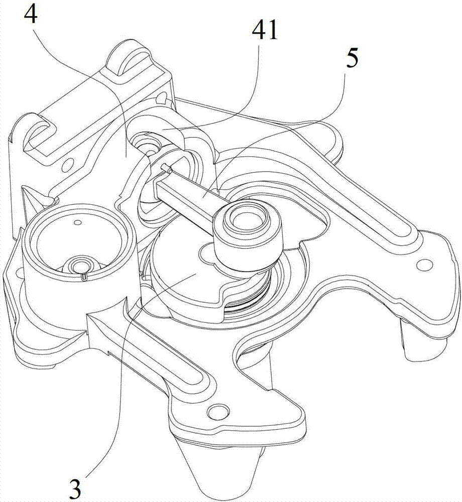
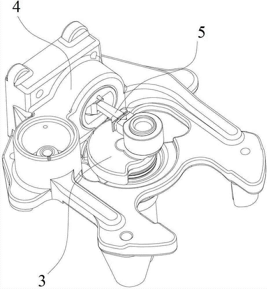
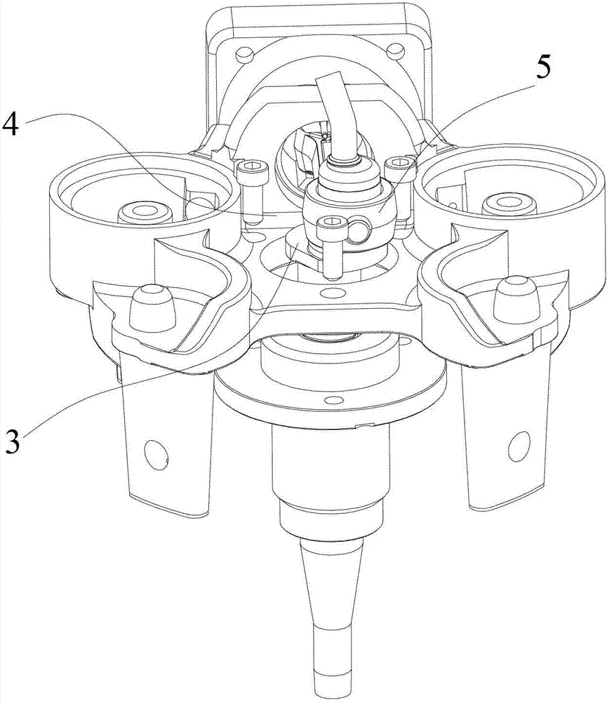
[0016] refer to Figure 4 , Figure 5 , the present invention provides a split crankshaft structure of a reciprocating compressor, including a split main shaft part 1 and a crank pin 2, one end of the main shaft part 1 is eccentrically docked with the crank pin 2 and a balance is provided on the opposite side of the crank pin 2 Block 11.

[0017] In the present invention, the crankshaft 3 adopts a split structure. When in use, the two ends of the connecting rod 5 are respectively connected with the piston in the cylinder block 4 and the crank pin 2 of the crankshaft 3, and then the crank pin 2 is fixedly connected with the main shaft part 1. , the structure maintains the structural integrity of the cylinder block 4 and the connecting rod 5, reduces the processing waste of the cylinder block 4, the connecting rod 5 and the crankshaft 3, saves the processing cost, and improves the productivity.

[0018] With the split crankshaft 3, there is no need to process the avoidance gro...


PUM


Abstract

The invention discloses a split crank shaft structure of a reciprocating compressor, which is applied to the field of reciprocating compressors. The split crank shaft structure comprises a main shaft part and a crank pin which are separated from each other, wherein one end of the main shaft part is in butt joint with the crank pin in an eccentric manner; and a balance block is arranged on the opposite side of the crank pin. According to the split crank shaft structure, a crank shaft adopts a split structure. When the structure is put into use, two ends of a connecting rod are respectively connected with a piston in a cylinder seat and the crank pin of the crank shaft, and then the crank pin is fixedly connected with the main shaft part. By the structure, the structural integrity of the cylinder seat and the connecting rod is kept, waste of processing of the cylinder seat, the connecting rod and the crank shaft is reduced, the processing cost is saved, and the production rate is improved.

Description

technical field [0001] The invention is used in the field of reciprocating compressors, and in particular relates to a crankshaft structure of a reciprocating compressor. Background technique [0002] The reciprocating compressor belongs to the volumetric compressor, which is a compressor that sequentially sucks and discharges a certain volume of gas into and out of a closed space. The crankshaft in the compressor drives the connecting rod, the connecting rod drives the piston, and the piston reciprocates. The movement of the piston changes the volume of the working chamber in the cylinder. When the piston moves from the outer dead center to the inner dead center, the intake valve opens and the exhaust valve is closed. The volume of the working chamber increases and the air is sucked in. When the piston When moving to the inner dead center, the intake valve is closed, the intake process is completed, and the volume of the working chamber reaches the maximum; as the cranksha...

Claims


Application Information

Patent Timeline
IPC IPC(8): F16C3/10F16C3/12
Inventor 陈东林凡林香
Owner WANBAO GROUP COMPRESSOR CO LTD
Why Eureka
Try Eureka