Electric power detection system

A technology of power detection and power, applied in the direction of control/regulation system, measuring power, measuring device, etc., can solve problems such as complex detection circuit configuration

Active Publication Date: 2015-07-15
DENSO CORP
View PDF4 Cites 1 Cited by
  • Summary
  • Abstract
  • Description
  • Claims
  • Application Information

AI Technical Summary

Problems solved by technology

[0005] In order to detect the remaining battery power of a mobile device, since the remaining battery power is detected by comparing the power supplied to the battery with the power consumed by the electric device, a complex detection circuit configuration is required

Method used


Image

  • Electric power detection system
  • Electric power detection system
  • Electric power detection system

Examples


Embodiment Construction

[0014] The power detection system will be described below with reference to one embodiment shown in the accompanying drawings.

[0015]

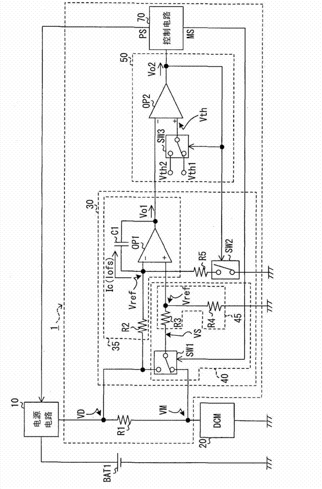
[0016] First refer to figure 1 , the power detection system 1 is provided to a device for monitoring and detecting power supplied from the on-vehicle battery BAT1 to an on-vehicle data communication module (DCM) 20 having a function of wirelessly communicating with an external communication device (not shown). The DCM 20 is applied to a system to which electric power is supplied from a battery BAT1 through a power supply circuit 10 including a DC / DC converter (not shown).

[0017] The power detection system 1 includes a detection resistor R1 , an integration circuit 30 , a comparison circuit 50 and a control circuit 70 . The detection resistor R1 is provided in a power supply path connecting the power supply circuit 10 and the DCM 20 . The integration circuit 30 outputs an integration output voltage Vo1 corresponding to the integration v...


PUM


Abstract

An integration circuit charges a capacitor by a charge current corresponding to a current flowing in a detection resistor provided in an electric power supply path extending to a DCM. A comparison circuit outputs a comparison signal, which changes to one of a high level and a low level in accordance with an integration value corresponding to a charge voltage of the capacitor. A discharge switch discharges the capacitor and stops discharge of the capacitor, when the comparison signal is at the high level and the low level, respectively. A control circuit determines an estimation value of electric power supplied from a battery to a DCM based on a count of edges, at which the signal level of the detection signal changes.

Description

technical field [0001] The present disclosure relates to a power detection system that detects the amount of power supplied to a power supply object. Background technique [0002] Existing mobile devices that run on batteries, such as laptops or cell phones, become inoperable due to low remaining battery power (battery depletion). In order to avoid this, it has been proposed to detect the remaining battery power of a mobile device by comparing the amount of power supplied from a power source to a storage battery built in the mobile device with the amount of power consumed by the mobile device (for example, JP2006-184035A) . [0003] Batteries are also installed in vehicles such as automobiles to supply electric power when the engine of the vehicle is started or when the amount of power generated by a generator (alternator) is insufficient. Recently, it is required to output electric power from the storage battery to the on-vehicle electrical equipment even when the ignitio...

Claims


Application Information

Patent Timeline
Patent Type & Authority Patents(China)
IPC IPC(8): G01R31/36
CPCG05F3/02G01R21/127
Inventor 石原俊郎
Owner DENSO CORP
Why Eureka
Try Eureka