
Array antenna radar cross section reduction method based on space mapping

A technology of radar scattering cross section and array antenna, which is applied in the directions of instruments, computing, electrical digital data processing, etc., can solve the problems that are difficult to describe and cannot realize the reduction of radar scattering cross section of large array antenna, so as to save time, save optimization time, and operate simple effect

Inactive Publication Date: 2013-08-14
NANJING UNIV OF SCI & TECH
View PDF2 Cites 17 Cited by
  • Summary
  • Abstract
  • Description
  • Claims
  • Application Information

AI Technical Summary

Problems solved by technology

However, for targets with complex structures, the traditional spatial mapping method will no longer converge because the coarse model does not have an analytical expression or the equivalent circuit is not easy to describe.

Method used


Image

  • Array antenna radar cross section reduction method based on space mapping
  • Array antenna radar cross section reduction method based on space mapping
  • Array antenna radar cross section reduction method based on space mapping

Examples


Embodiment 1

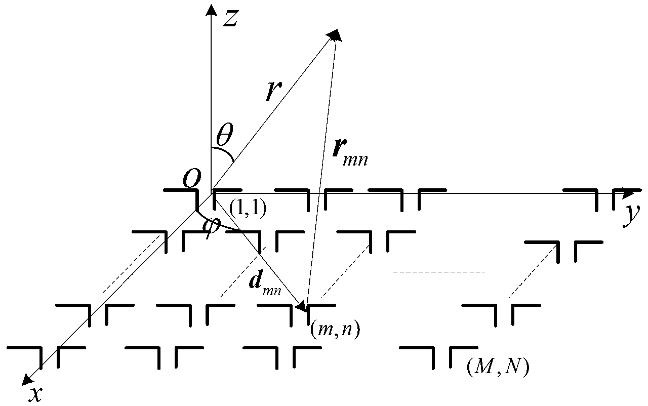
[0083] In order to verify the correctness and effectiveness of the method in this paper, the following analyzes the selection of the array antenna as follows: figure 1 A 6×6 element planar array is arranged, that is, M=6, N=6, and the antenna unit is a half-wave dipole antenna with a working frequency of 1 GHz. Antenna element spacing and optimization in the range of [0.55λ g ,λ g ] mm between. The calculation example is implemented on a personal computer with a main frequency of 1.86GHz and a memory of 2GB.

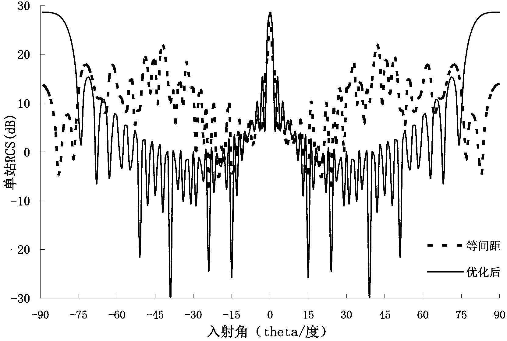
[0084] figure 2 The dotted line indicates that the antenna elements are equally spaced (the antenna element spacing in the x-axis direction is 0.5λ g mm, the antenna element spacing in the y-axis direction is 0.5λ g mm), the solid line represents the calculation result after the distance is optimized in the present invention, it can be seen that in most angle domains where the incident angle is -90°≤φ≤90°, the single-station RCS of the antenna is higher than that...


PUM


Abstract

The invention discloses an array antenna radar cross section reduction method based on space mapping. The array antenna radar cross section reduction method based on the space mapping comprises the steps of establishing an array antenna model, enabling unit amplitude uniform plane wave to illuminate on an array antenna, and determining a total scattering field of the array antenna; deducing a radar cross section formula of the array antenna according to a pattern multiplication, establishing a space mapping rough model of the array antenna, optimizing the rough model and determining an optimum design parameter of the rough model; utilizing a method of moments of a full-wave analysis in a fine model; enabling the response of the rough model to approach that of the fine model through parameter extraction, and establishing a mapping relation of a rough model parameter and a fine model parameter; and utilizing the optimum design parameter of the rough model and the inverse mapping of the established mapping relation to obtain a prediction parameter of the fine model, and if the prediction parameter of the fine model does not meet a design requirement, subjecting the mapping relation to iteration updating until the prediction parameter of the fine model meets the design requirement. The array antenna radar cross section reduction method based on the space mapping subjects the design parameter to a global optimization and saves time under the premise of guaranteeing the accuracy.

Description

a technical field [0001] The invention belongs to the technical field of radar scattering cross-section reduction, in particular to a method for reducing the radar scattering cross-section of an array antenna based on space mapping. Two background technology [0002] With the development of detection technology, the reduction of target radar cross section RCS is undoubtedly of great military significance. Effective stealth design of large array antennas must rely on powerful electromagnetic scattering calculation methods. In the past, the research work on the scattering characteristics of array antennas mostly relied on numerical algorithms such as the method of moments or commercial software based on numerical algorithms. However, when the scale of the array antenna is too large, such methods will consume a lot of computing resources and time. [0003] Applying traditional methods to reduce the radar cross section of large array antennas is facing challenges. First, it is ...

Claims


Application Information

Patent Timeline
Patent Type & Authority Applications(China)
IPC IPC(8): G06F17/50
Inventor 陈如山丁大志樊振宏徐娟沙侃叶晓东李兆龙盛亦军
Owner NANJING UNIV OF SCI & TECH
Learn More