Replaceable channel structure

A channel structure and channel technology are applied in the field of removable channel structures to achieve the effects of eliminating leakage, reducing costs, highlighting installation convenience and sealing reliability

Active Publication Date: 2013-08-14
NUCLEAR POWER INSTITUTE OF CHINA
View PDF10 Cites 2 Cited by
  • Summary
  • Abstract
  • Description
  • Claims
  • Application Information

AI Technical Summary

Problems solved by technology

Now, the difficulty in conducting this experiment is that there is a lack of a device that can be disassembled and changed the cooling channel structure of the simulated body

Method used


Image

  • Replaceable channel structure
  • Replaceable channel structure
  • Replaceable channel structure

Examples


Embodiment 1

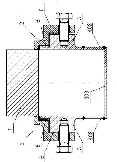
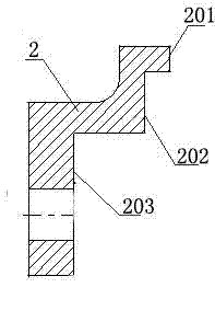
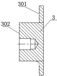
[0033] Such as figure 2 As shown, a removable channel structure mainly includes a metal body 1, a connecting piece 2, a sealing piece 3 and a lower sealing structure 4; the connecting piece 2 is symmetrically arranged on both sides of the metal body 1; the sealing piece 3 can pass through The disassembly connection is connected with the connecting part 2, the sealing part 2 is located under the metal body 1 in whole or in part; the lower sealing structure 4 is connected with the bottom of the sealing part 3; the connecting part 2, the sealing part 3 and the lower sealing part 4 are all along the metal body The direction of the axis of the body 1 extends to both ends of the metal body 1; the bottom surface of the metal body 1, the connecting piece 2, the sealing piece 3 and the lower sealing structure 4 jointly form a channel with openings at both ends.

[0034] When using this embodiment, the cooling liquid is passed through the channel to cool the metal body 1, so as to real...

Embodiment 2

[0039] In this embodiment, on the basis of the above-mentioned embodiments, the thermal conductivity of the materials constituting the connecting member 2 , the sealing member 3 and the lower sealing structure 4 is smaller than that of the material constituting the metal body 1 . In this embodiment, considering the weldability between the connecting piece 2 and the metal body 1, if the metal body 1 is made of copper, the connecting piece 2, the sealing piece 3 and the lower sealing structure 4 are preferably made of stainless steel. The thermal conductivity of copper is much higher than that of stainless steel, and the thermal conductivity of stainless steel is also low. Therefore, less heat is taken away through the connecting piece 2, the sealing piece 3 and the lower sealing structure 4. Only by letting the cooling water in the channel take away the heat of the metal body 1 can more accurate experiments be conducted on the influence of various geometric structure parameters ...

Embodiment 3

[0042] Such as figure 2 As shown, on the basis of the above embodiments, this embodiment further includes a gasket 6, which is compressed between the connecting part 2 and the sealing part 3, and the gasket 6 is made of a flexible sealing material. In this embodiment, the constituent material of the sealing gasket 6 is preferably silicon rubber, and other flexible sealing materials such as fluororubber, nitrile rubber, butyl rubber, etc. can also be used in the present invention.


PUM


Abstract

The invention discloses a replaceable channel structure mainly comprising a metal body, connecting pieces, sealing pieces and a lower sealing and isolating structure. The connecting pieces are symmetrically arranged at two sides of the metal body; the sealing pieces are detachably connected with the connecting pieces, the entire or part of the sealing pieces is located under the metal body; the lower sealing and isolating structure is connected with the bottoms of the sealing pieces; the connecting pieces, the sealing pieces and the lower sealing and isolating structure all extend to two ends of the metal body along the axis of the metal body; and the bottom surface of the metal body, the connecting pieces, the sealing pieces and the lower sealing and isolating structure jointly form a channel, wherein the two ends of the channel are opened. The replaceable channel structure has the advantages and the positive effects of realizing the experiment of influence on metal body critical heat flux and external surface flow and heat transfer features caused by various cooling flow channel geometry structure parameters under the condition of convenience and low cost.

Description

technical field [0001] The invention relates to the field of nuclear industry, in particular to a detachable channel structure. Background technique [0002] During the design process of new generation nuclear reactors, more and more attention is paid to ensuring the integrity of the reactor pressure vessel. The above design ideas are based on summarizing many serious nuclear leakage accidents that have occurred around the world. By analyzing the causes and deterioration process of the Three Mile Island nuclear accident in the United States, the Chernobyl nuclear accident in the former Soviet Union, and the Fukushima nuclear leakage accident in Japan, it can be found that the reactor core melt remains in the pressure vessel to ensure that the reactor pressure vessel The integrity of the system can greatly alleviate the further development and deterioration of serious accidents. [0003] Now, there is a relatively complete reactor melt retention strategy, and the key points...

Claims


Application Information

Patent Timeline
Patent Type & Authority Applications(China)
IPC IPC(8): G21C15/14
CPCY02E30/40Y02E30/30
Inventor 张震熊万玉王雄卓文彬李朋洲韩群霞张兴武
Owner NUCLEAR POWER INSTITUTE OF CHINA
Why Eureka
Try Eureka