Eureka AIR delivers breakthrough ideas for toughest innovation challenges, trusted by R&D personnel around the world.

Leakage protection method and system of redox flow cell system as well as redox flow cell system

A flow battery, leakage protection technology, applied in fuel cell additives, regenerative fuel cells, etc., can solve the problems of heat treatment burden, damage to the stack, large size, etc., to simplify and facilitate post-maintenance, save hardware costs, and extend service life. Effect

Active Publication Date: 2013-08-14
DALIAN RONGKE POWER
View PDF4 Cites 9 Cited by
  • Summary
  • Abstract
  • Description
  • Claims
  • Application Information

AI Technical Summary

Problems solved by technology

[0002] Due to its performance advantages, flow batteries have become one of the preferred technologies for large-scale energy storage applications. However, due to the existence of public pipelines and conductive media, leakage current has become a unique disadvantage of all-vanadium flow batteries. The leakage current is converted in the form of heat. It will increase the temperature of the electrolyte, which will bring a burden to the heat treatment of the flow battery, especially when the flow battery is powered off, the electric energy in the stack will be released in the form of leakage, and the electrolyte does not flow at this time, so that Its temperature rises rapidly and exceeds the tolerance range of the stack material, which will inevitably cause damage to the stack material and damage the stack. Therefore, it is necessary to minimize the damage caused by leakage current, prolong the life of the flow battery and ensure the excellent performance of the flow battery , the patent application No. 201110304909.2 proposes a method for shutdown protection of a flow battery. This method connects the stack to an external resistor. The liquid is slowly discharged to protect the flow battery system, but the method mentioned in this patent application needs to be realized by connecting multiple external resistors. For large-scale flow battery systems, such as megawatt-level flow battery systems, due to its The number of stacks is as many as hundreds, and this method requires more external auxiliary equipment, which makes the flow battery system more complex and large, and the subsequent maintenance and repair of the battery system will also bring a series of problems

Method used


Image

  • Leakage protection method and system of redox flow cell system as well as redox flow cell system
  • Leakage protection method and system of redox flow cell system as well as redox flow cell system
  • Leakage protection method and system of redox flow cell system as well as redox flow cell system

Examples


Embodiment Construction

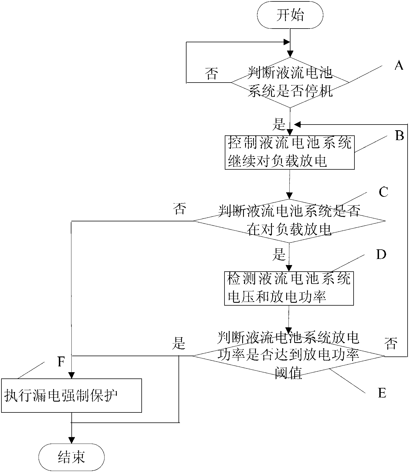
[0036] Such as figure 1 A leakage protection method for a liquid flow battery system includes the following steps:

[0037] A: After starting, judge whether the flow battery system is shut down, if yes, execute step B, otherwise return to start;

[0038] B: Control the flow battery system to continue discharging the load, and execute step C;

[0039] C: Determine whether the flow battery system is discharging the load, if yes, execute step D, otherwise execute step F;

[0040] D: Detect the voltage and discharge power of the flow battery system, and execute step E;

[0041] E: Determine whether the discharge power of the flow battery system reaches the discharge power threshold, if yes, execute step F or end, otherwise execute step B;

[0042] F: Execute mandatory leakage protection, end;

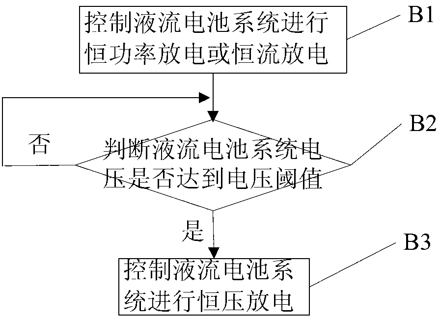
[0043] As preferred, such as figure 2 As shown, step B specifically includes the following steps:

[0044] B1: Control the flow battery system to perform constant power discharge or ...


PUM


Abstract

The invention discloses a leakage protection method and system of a redox flow cell system as well as the redox flow cell system. The method comprises the following steps of: A, judging whether the redox flow cell system is powered off or not after the redox flow cell system is started, executing the step B if yes, otherwise, returning to the starting step; B, controlling the redox flow cell system to continue discharging a load, and executing the step C; C, judging whether the redox flow cell system discharges the load or not, executing the step D if yes, otherwise, executing the step F; D, detecting the voltage and discharging power of the redox flow cell system, and executing the step E; E, judging whether the discharge power of the redox flow cell system reaches a discharge power threshold value or not, executing the step F or ending if yes, otherwise, executing the step B; and F, executing the forced leakage protection, and ending. Due to the adoption of the leakage protection method, the leakage protection system and the redox flow cell system, the structure is simple, the hardware cost saved, and the later maintenance is simplified and convenient; and through the forced protection means, the redox flow cell system can perform the discharge operation under any condition, so that the service life of the redox flow cell system can be fundamentally prolonged.

Description

technical field [0001] The invention relates to a leakage protection method and system for a liquid flow battery system and a liquid flow battery system. Background technique [0002] Due to its performance advantages, flow batteries have become one of the preferred technologies for large-scale energy storage applications. However, due to the existence of public pipelines and conductive media, leakage current has become a unique disadvantage of all-vanadium flow batteries. The leakage current is converted in the form of heat. It will increase the temperature of the electrolyte, which will bring a burden to the heat treatment of the flow battery, especially when the flow battery is powered off, the electric energy in the stack will be released in the form of leakage, and the electrolyte does not flow at this time, so that Its temperature rises rapidly and exceeds the tolerance range of the stack material, which will inevitably cause damage to the stack material and damage the...

Claims


Application Information

Patent Timeline
IPC IPC(8): H01M8/04H01M8/18
CPCY02E60/528Y02E60/50
Inventor 马相坤张华民许晓波吴静波权颖赵亮
Owner DALIAN RONGKE POWER
Why Eureka
Eureka Blog
Learn More