UV laser exposure of housings and components of door drives and door closers

A door closer and housing technology, applied in the field of door operators or door closers, can solve problems such as disturbing noise, affecting the operation of door operators or door closers, etc., and achieve the effect of high strength and smooth surface finish

Inactive Publication Date: 2013-08-14
DORMA GMBH & CO KG
View PDF8 Cites 0 Cited by
  • Summary
  • Abstract
  • Description
  • Claims
  • Application Information

AI Technical Summary

Problems solved by technology

From this, the resulting friction may produce noises that can be considered disturbing
In addition, wear and tear may occur, which may adversely affect the operation of the door operator or door closer

Method used


Image

  • UV laser exposure of housings and components of door drives and door closers
  • UV laser exposure of housings and components of door drives and door closers
  • UV laser exposure of housings and components of door drives and door closers

Examples


Embodiment Construction

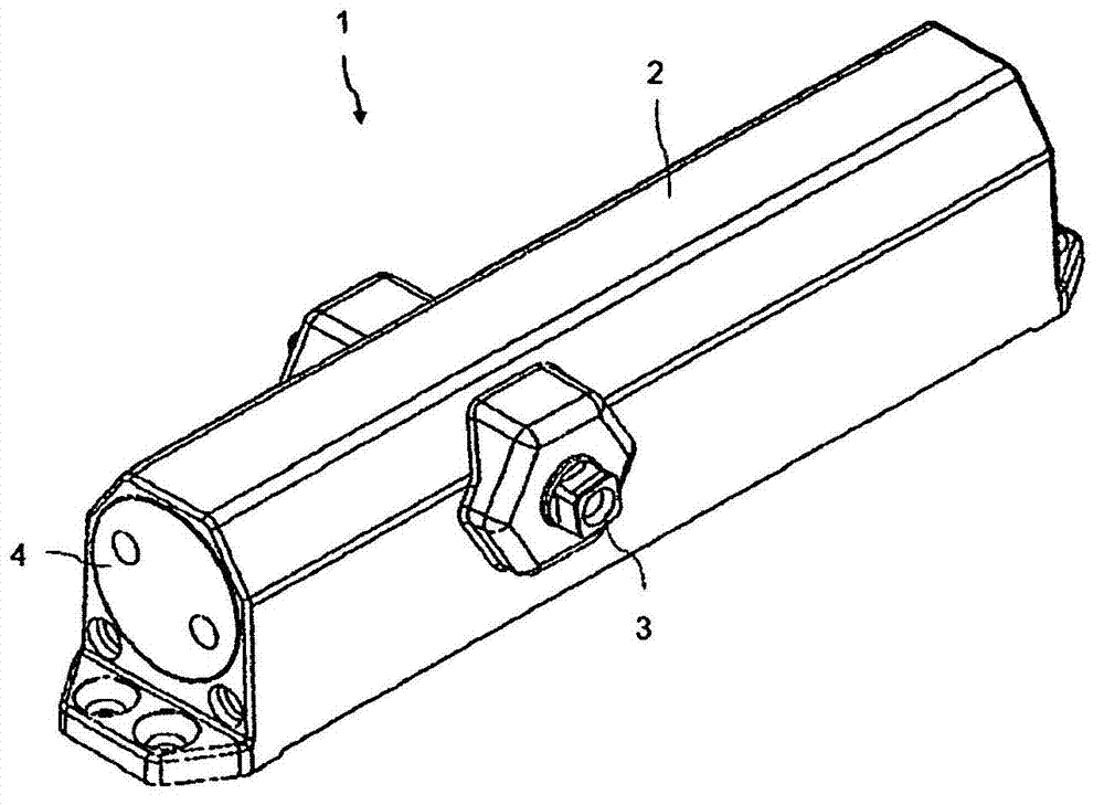
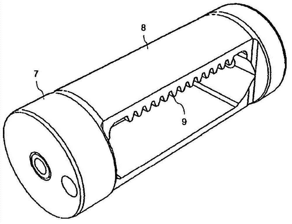
[0016] exist figure 1 A schematic perspective view of an embodiment of the inventive door closer 1 is shown in . In this case, the mechanical components of the door closer 1 are surrounded by a housing 2 . The interior of the housing 2 is accessible via a screwable end plate 4 . Inside the door closer 1 , the mechanical parts are actuated by means of the shaft 3 . The (not visible) piston 7 is held movably in the receiving unit 5 of the housing 2 and is driven via the shaft 3 . Due to the inventive treatment of the surface 8 of the piston 7 and the surface 6 of the receiving unit 5 respectively, the friction between the structural parts of the door closer 1 is reduced. Therefore, the high wear resistance and lifespan of the door closer 1 can be improved.

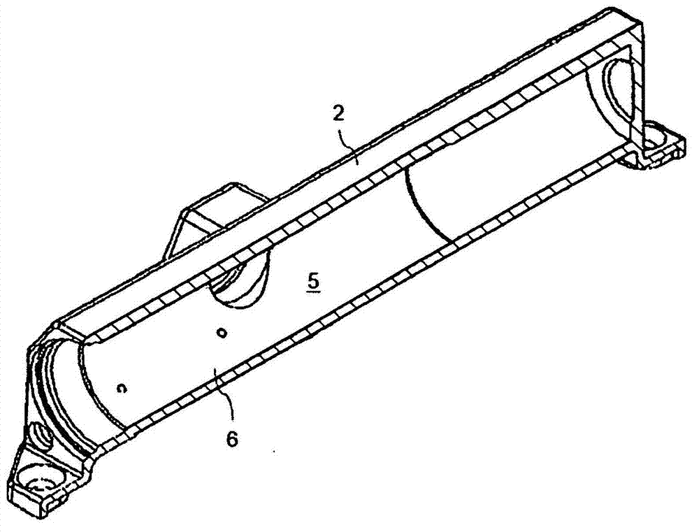
[0017] figure 2 shows the basis figure 1 A schematic perspective sectional view of the housing 2 of the inventive door closer 1 . Other structural components are not shown. The inner peripheral surface 6 of the rece...


PUM


Abstract

The invention relates to a door drive or door closer (1), having at least one housing (2) and at least one piston (7) mounted in a receiver (5) of the housing (2), wherein the surfaces (6, 8) of the receiver (5) and / or of the at least one piston (7) are treated by exposure to electromagnetic radiation.

Description

technical field [0001] The invention relates to a door operator or door closer, wherein the door operator or door closer comprises at least one housing, a receiving unit and at least one piston supported so as to be movable in the receiving unit. Background technique [0002] A door operator is a device for automatically opening and closing a door. The door may eg be a swing leaf door or a sliding door. However, door closers are only used to automatically close doors. In this case, in particular the movement of the door leaf into the door frame or in relation to the door frame, the door operator or door closer acts. It is known to implement door operators or door closers in such a way that the cylindrical receiving unit is located in the housing of the door operator or door closer. A piston is supported to be movable in the receiving unit. Especially in door closers, once the door is opened, the movement of the piston has the effect of tensioning the spring or energizing...

Claims


Application Information

Patent Timeline
Patent Type & Authority Applications(China)
IPC IPC(8): C21D1/06C21D1/09C21D1/10C21D9/14
CPCE05Y2800/45E05Y2201/454E05Y2800/43C21D1/06C21D9/14E05F1/00C21D1/09E05F3/10E05Y2900/132C21D1/10E05Y2201/456E05F3/227Y02P10/25
Inventor 蒂姆·武尔勃兰特
Owner DORMA GMBH & CO KG
Why Eureka
Try Eureka