Mixed gas generation device
A technology of mixing gas and generating device, which is applied in the production of hydrogen, organic production of electrolysis, electrolysis components, etc., can solve the problems of limited burial amount, etc., and achieve the effect of improving energy efficiency
- Summary
- Abstract
- Description
- Claims
- Application Information
AI Technical Summary
Problems solved by technology
Method used
Image
Examples
Embodiment approach 1
[0043] [Structure of electrolysis device]
[0044]First, the configuration of the electrolysis device according to Embodiment 1 of the present invention will be briefly described. The electrolysis device of this embodiment is equipped with: the interior is filled with dissolved CO 2 The electrolytic cell of the electrolytic solution; the working electrode (WE), the counter electrode (CE) and the reference electrode (RE) installed in the electrolytic cell; a potentiostat configured to change the voltage of WE relative to RE. Since these components are components of a known electrolysis device, description thereof will be omitted.
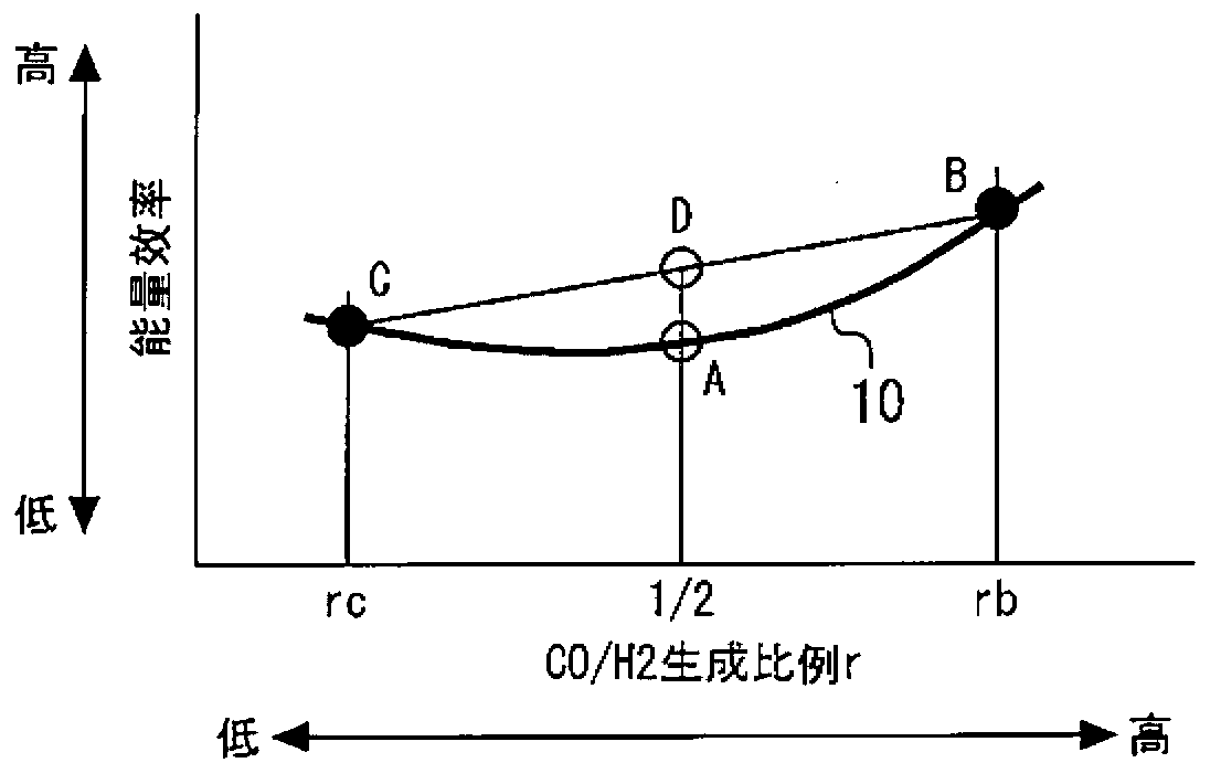
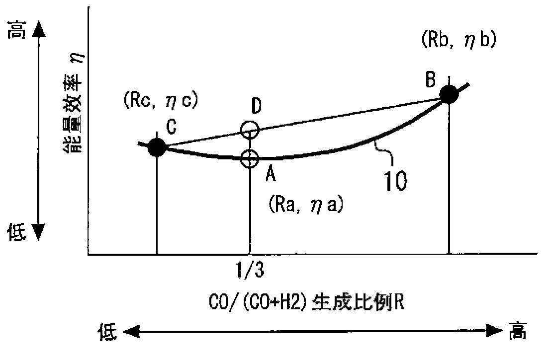
[0045] In addition, the electrolysis device of the present embodiment is equipped with a control device that controls the voltage regulator to flow a predetermined current value between WE and CE to maintain the voltage of WE with respect to RE at a set value. In the internal memory of this control device, a set value of a voltage corresponding to ...
Embodiment approach 2
[0081] [Structure of electrolysis device]
[0082] Next, an electrolysis device according to Embodiment 2 of the present invention will be described. The electrolysis device of this embodiment is different from the configuration of the electrolysis device of Embodiment 1 above in that two electrolysis cells are provided. Therefore, since each component is basically the same as that of Embodiment 1 except for this point, description thereof will be omitted.
[0083] In the first embodiment described above, electrolysis was performed at the operation points B and C using one electrolytic tank. However, since the operating points B and C cannot be set at the same time, it is necessary to perform control to switch the operating point from B to C (or from C to B) at a certain point of time. In this regard, according to the present embodiment in which two electrolytic cells are provided, electrolysis at the operation point B and electrolysis at the operation point C can be perform...
Embodiment approach 3
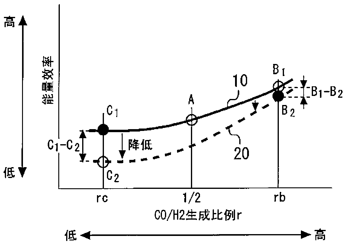
[0086] Second, refer to image 3 Embodiment 3 of the present invention will be described. The present embodiment is characterized in that the order of electrolysis is determined according to the degree of reduction in energy efficiency by performing electrolysis using the structure of the above-mentioned first embodiment. Therefore, since each component is common to that of Embodiment 1 described above, description thereof will be omitted.
[0087] As described in Embodiment 1, when the voltage regulator is controlled so that a current flows between WE and CE, the reactions of the above formulas (1) to (3) are performed. If the reactions of the above-mentioned formulas (1) to (3) proceed, the reaction substances in the electrolytic solution will decrease. For example, if the reaction of the above formula (1) is carried out, the CO in the electrolyzer 2 Decrease, if the reaction of the above formula (2) is carried out, the protons will decrease. Thus, the concentration of t...
PUM
 Abstract
Description
Claims
Application Information
 - R&D
- Intellectual Property
- Life Sciences
- Materials
- Tech Scout
- Unparalleled Data Quality
- Higher Quality Content
- 60% Fewer Hallucinations
Browse by: Latest US Patents, China's latest patents, Technical Efficacy Thesaurus, Application Domain, Technology Topic, Popular Technical Reports.
© 2025 PatSnap. All rights reserved.Legal|Privacy policy|Modern Slavery Act Transparency Statement|Sitemap|About US| Contact US: help@patsnap.com


