Industrial self-iagnostic device

An automatic diagnosis and industrial technology, applied in measuring devices, general control systems, program control, etc., can solve problems such as knowledge complexity and achieve the effect of automation

Inactive Publication Date: 2013-08-14
MITSUBISHI ELECTRIC CORP
View PDF9 Cites 1 Cited by
  • Summary
  • Abstract
  • Description
  • Claims
  • Application Information

AI Technical Summary

Problems solved by technology

However, most FA systems have a hierarchical structure that combines multiple networks, and the connection settings accompanying abnormality diagnosis and the knowledge required for abnormality diagnosis are complicated.

Method used


Image

  • Industrial self-iagnostic device
  • Industrial self-iagnostic device
  • Industrial self-iagnostic device

Examples


Embodiment approach 1

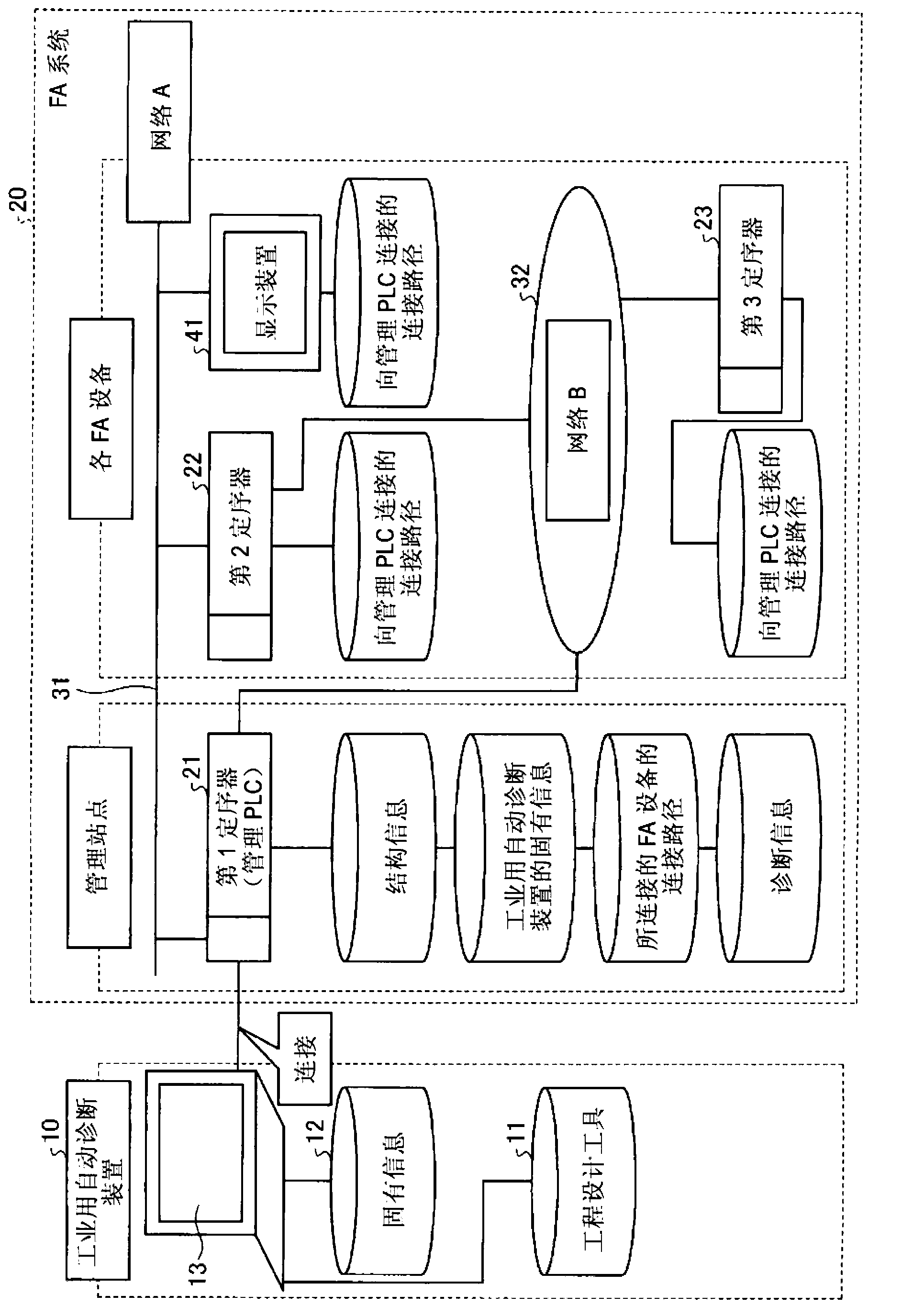
[0024] figure 1 It is a diagram showing the configuration of the FA system 20 according to the embodiment of the present invention and the industrial automatic diagnostic device 10 connected thereto. The industrial automatic diagnosis device 10 (abnormality diagnosis device) is, for example, a personal computer (personal computer), which is equipped with an engineering tool 11 and has a display 13 as a display means for displaying to a user. In addition, the display means for displaying to the user does not have to be the display 13 , and is not particularly limited as long as it is a display means that the user can understand at a glance, for example, in a printout format.

[0025] The engineering design tool 11 performs, for the FA system 20, programming, program monitoring, system construction, display / setting / tracking of data values, and status monitoring / operation of each FA device and the lower-level devices that constitute each FA device. and other software.

[0026] ...


PUM


Abstract

An industrial automatic-diagnostic device connected to an FA system in which a plurality of FA devices are connected to each other, the industrial automatic-diagnostic device includes: an engineering tool; and a display unit. Based on interface connection information and device configuration information of a corresponding FA device held by each of the FA devices, the engineering tool creates overall configuration information of the FA system and displays an overall configuration of the FA system on the display unit based on the overall configuration information. When an abnormality occurs in the FA device, diagnosis information about an abnormal part self-diagnosed by the FA device and abnormality contents with respect to the abnormality occurred in a corresponding abnormal part is obtained. Based on the obtained diagnosis information, occurrence of an abnormality is displayed in an abnormal part in an overall configuration of the FA system displayed on the display unit.

Description

technical field [0001] The invention relates to an industrial automatic diagnosis device realized by engineering tools. Background technique [0002] In recent years, maintenance of FA (Factory Automation) systems has required that even engineers with little experience can easily diagnose abnormalities. However, most FA systems have a hierarchical structure in which a plurality of networks are combined, and connection settings accompanying abnormality diagnosis and knowledge required for abnormality diagnosis are complicated. [0003] Regarding a system using a PLC (Programmable Logic Controller: sequencer) etc. as a system structural element, a technique has been disclosed in which one of the PLCs connected via a network is positioned as a station for sending setting information, and a portable tool is used to A distributed control system that saves frame structure data through a memory card (see Patent Document 1), or an abnormality diagnosis system that automatically det...

Claims


Application Information

Patent Timeline
Patent Type & Authority Applications(China)
IPC IPC(8): G05B23/02
CPCG05B19/042G01R31/3187G05B23/0267G05B23/02
Inventor 堀川朋大庭邦夫渡部拓
Owner MITSUBISHI ELECTRIC CORP
Why Eureka
Try Eureka