Soil material separator for argil batch packaging

A separator and soil material technology, which is applied in ceramic molding machines, packaging material feeding devices, packaging, etc., can solve the problems of troublesome manual operation and difficulty in equal distribution of materials, so as to improve work efficiency, reduce errors and save manpower. Effect

Active Publication Date: 2021-02-12
山东连环机械科技有限公司
View PDF7 Cites 1 Cited by
  • Summary
  • Abstract
  • Description
  • Claims
  • Application Information

AI Technical Summary

Problems solved by technology

[0004] In order to overcome the current manual operation is more troublesome, and the shortcomings of equal distribution of materials are difficult, the technical problem

Method used


Image

  • Soil material separator for argil batch packaging
  • Soil material separator for argil batch packaging
  • Soil material separator for argil batch packaging

Examples


Embodiment 1

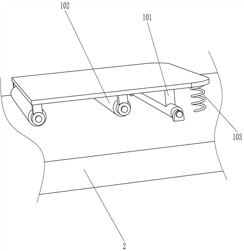
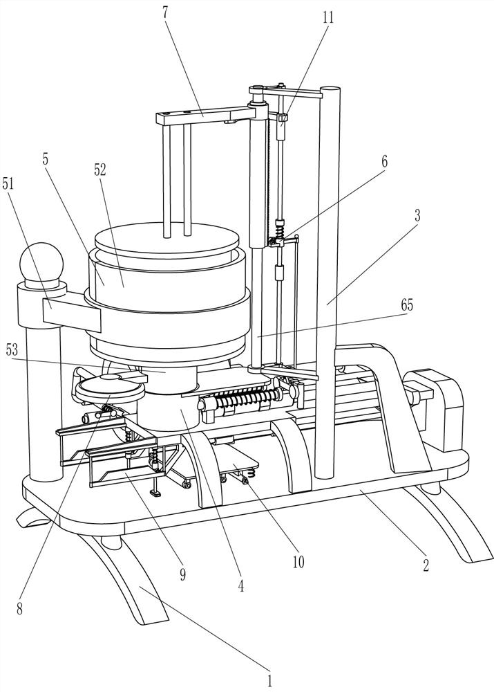
[0091] A soil material separator for batch packing of pottery clay, such as figure 1 As shown, it includes a base 1, an operating table 2, a mounting frame 3, a discharge mechanism 4, a charging mechanism 5, an intermittent pushing mechanism 6 and an extruding mechanism 7. An operating table 2 is connected between the top of the base 1, and the operating table 2 The right front side is connected with a mounting frame 3, the left side of the console 2 is connected with a discharge mechanism 4, the left rear side of the console 2 is connected with a charging mechanism 5, and an intermittent push mechanism 6 is connected between the mounting frame 3 and the discharge mechanism 4. A pressing mechanism 7 is connected between the installation frame 3 and the intermittent pushing mechanism 6 .

[0092] When people need to pack the pottery clay in batches, they first pour the pottery clay into the charging mechanism 5, start the discharge mechanism 4, and the discharge mechanism 4 dri...

Embodiment 2

[0094] On the basis of Example 1, such as figure 1 , figure 2 and Figure 4 As shown, the discharge mechanism 4 includes a horizontal plate 41, a first guide sleeve 42, a first guide rod 43, a discharge ring 44, a first spring 45, a baffle plate 46, an electric push rod 47, a connection, a second guide rod 49. The second guide sleeve 410 and the contact plate 411, the top of the console 2 is connected with a horizontal plate 41, the top of the left side of the horizontal plate 41 is connected with the first guide sleeve 42 on the front and rear sides, and the first guide sleeve 42 is slidingly connected There is a first guide rod 43, a discharge ring 44 is connected between the left side of the first guide rod 43, a first spring 45 is connected between the right side of the first guide sleeve 42 and the first guide rod 43, and the first spring 45 Set on the outside of the first guide rod 43, the upper right side of the discharge ring 44 is connected with a baffle 46, the le...

Embodiment 3

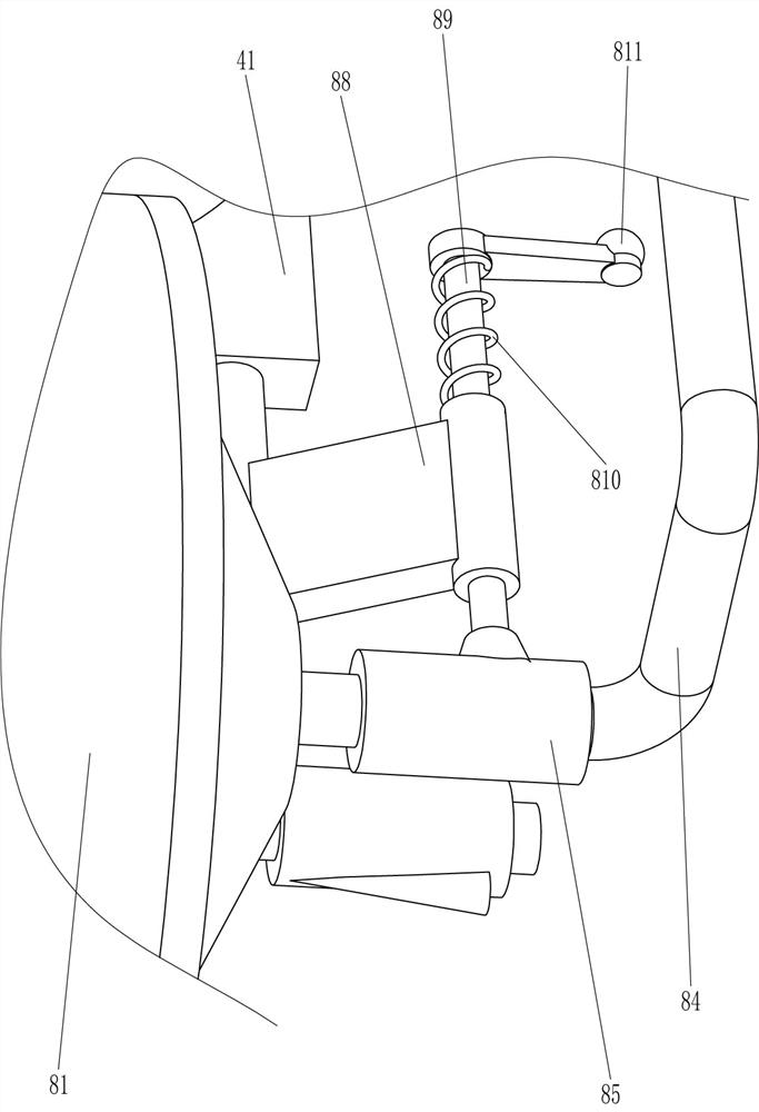
[0099] On the basis of Example 2, such as figure 2 , image 3 , Figure 4 , Figure 5 , Figure 6 , Figure 7 , Figure 8 and Figure 9 As shown, the intermittent pushing mechanism 6 includes a stay cord 61, a guide wheel 62, a fixed mount 63, a first guide rod 64, a second guide rod 65, a guide ring 66, a stabilizer 67, a pawl 68, a second spring 69, Helical rack 610 and the 3rd spring 611, mounting frame 3 bottoms are connected with fixed mount 63, and fixed mount 63 rear portion right side rotation type is connected with lead wheel 62, and fixed mount 63 left top is connected with second guide bar 65, fixes A first guide rod 64 is connected in the middle of the rear side of the frame 63, and a guide ring 66 is slidably connected to the first guide rod 64. A stay cord 61 is connected between the right side of the guide ring 66 and the top of the contact plate 411, and the stay cord 61 bypasses the Guide wheel 62, guide ring 66 left side is connected with stabilizing ...


PUM


Abstract

The invention relates to a soil material separator, in particular to a soil material separator for argil batch packaging. Through the provided soil material separator for argil batch packaging, automatic extrusion forming of argil can be achieved, and the packaged argil can be taken out. The provided soil material separator for argil batch packaging comprises a base, an operation table, a mountingframe, a discharging mechanism, a charging mechanism and an intermittent pushing mechanism. The operation table is connected between the tops of the base. One side of the operation table is connectedwith the mounting frame. One side of the operation table is connected with the discharging mechanism. The operation table is connected with the charging mechanism. The intermittent pushing mechanismis connected between the mounting frame and the discharging mechanism. An extrusion mechanism is connected between an extrusion mechanism mounting frame and the intermittent pushing mechanism. Throughcooperation of the discharging mechanism, the charging mechanism, the intermittent pushing mechanism and the extrusion mechanism, the argil can be automatically extruded downwards, meanwhile, the argil moves leftwards after extrusion forming, the argil is collected, and therefore an automatic effect can be achieved.

Description

technical field [0001] The invention relates to a soil material separator, in particular to a soil material separator for packing pottery clay in batches. Background technique [0002] Ceramics are generally made of clay and shaped by fire. Clay is a ceramic raw material with complex mineral components, mainly silt-sandy clay composed of hydromica, kaolinite, montmorillonite, quartz and feldspar. When making ceramics, the pottery clay will be separated in equal amounts, because when making products, the amount of pottery clay needed must be equal, so that products of the same size can be made. [0003] For the operation of distributing clay, there is no corresponding equipment on the market at present. It is divided by tools and manual materials. The clay is packed in a cylindrical tube, and then the clay is extruded and taken out downwards. This operation is more troublesome, and It is difficult to divide the materials equally, so now we have developed a soil material sep...

Claims


Application Information

Patent Timeline
IPC IPC(8): B28B3/20B28B17/00B65B41/04B65B41/10B65B49/00
CPCB28B3/20B28B17/00B65B41/04B65B41/10B65B49/00
Inventor 林文斌
Owner 山东连环机械科技有限公司
Why Eureka
Try Eureka