Construction method for side-slope platform pile-adding in-situ soil gravity-type retaining wall

A construction method and in-situ soil technology, applied in underwater structures, infrastructure engineering, water conservancy engineering, etc., can solve the problems of masonry costs, spoil pollution, unfavorable slope stability in the early stage, and achieve good overall stability. , the effect of reducing the project cost and protecting the original vegetation

Inactive Publication Date: 2013-08-21
SOUTHWEST JIAOTONG UNIV
View PDF4 Cites 0 Cited by
  • Summary
  • Abstract
  • Description
  • Claims
  • Application Information

AI Technical Summary

Problems solved by technology

The traditional retaining wall needs to excavate the slope toe, which will cause masonry costs and is not conducive to the early stability of the slope; and it is easy to form spoil pollution, which cannot meet the requirements of economy and environmental protection. Therefore, an economical and environmentally friendly slope treatment measure is urgently needed

Method used


Image

  • Construction method for side-slope platform pile-adding in-situ soil gravity-type retaining wall
  • Construction method for side-slope platform pile-adding in-situ soil gravity-type retaining wall
  • Construction method for side-slope platform pile-adding in-situ soil gravity-type retaining wall

Examples


Embodiment Construction

[0010] The present invention will be further described below in conjunction with the accompanying drawings and specific implementation.

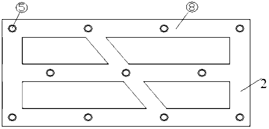
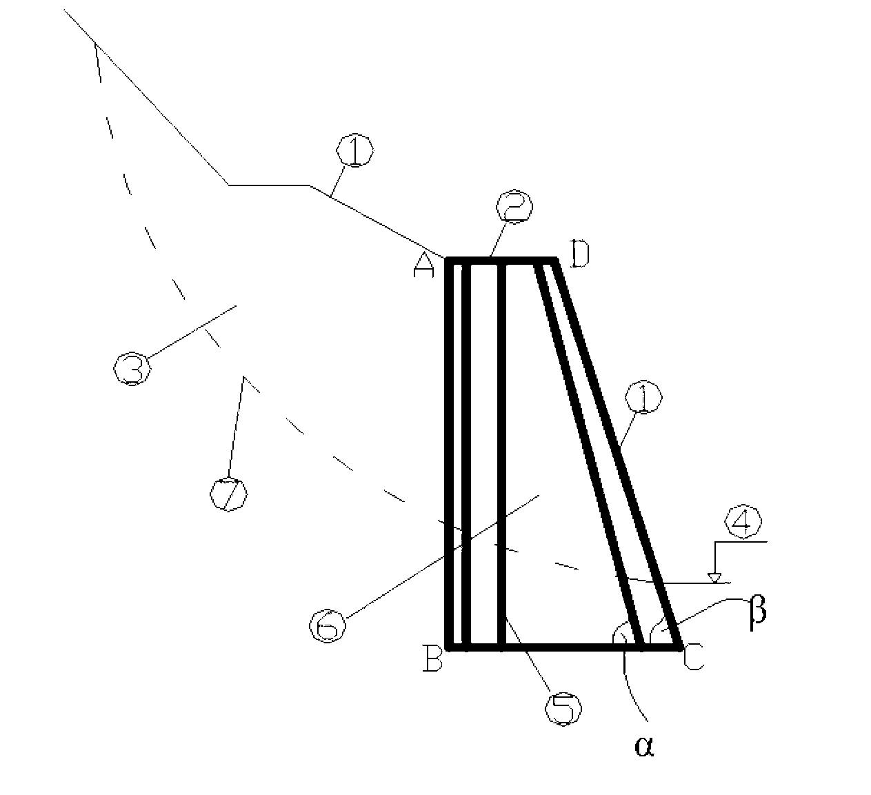
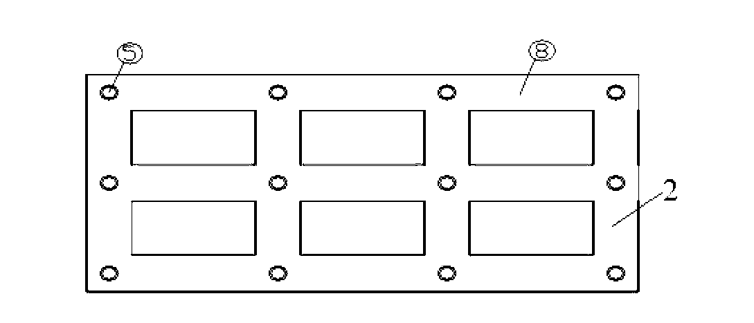
[0011] In-situ soil gravity retaining wall with piles added to slope platform figure 1 , where the ABCD area constitutes the retaining wall, and the entire retaining wall is composed of steel flower tubes ⑤, in-situ soil ⑥ and connecting beams ⑧ on the surface of the platform ②.

[0012] In the figure: ①slope ②first-level platform ③sliding mass ④ground ⑤steel pipe ⑥in-situ soil ⑦potential sliding surface ⑧connecting beam.

[0013] The construction includes the following steps: after leveling the site on the slope platform, after setting out the hole position, drilling the steel flower pipe hole, and adopting the grouting steel flower pipe technology after cleaning the hole: inserting the steel flower pipe, pressure grouting; excavating on the slope platform above the steel flower pipe The formwork groove of the contact beam is bound, and th...


PUM


Abstract

The invention discloses a construction method for a side-slope platform pile-adding in-situ soil gravity-type retaining wall. The construction method is characterized in that a primary side-slope in-situ soil body is reinforced by a grouting steel perforated tube technology to form the retaining wall. The construction method includes the following steps: leveling land of a side-slope platform, lofting hole locations, drilling holes of steel perforated tubes, adopting the grouting steel perforated tube technology after cleaning the holes, inserting the steel perforated tubes, grouting by pressure, excavating contact beam framework grooves on the side-slope platform on the upper portion of the steel perforated tubes, strapping steel reinforcement cages, forming an entire contact beam after casting, and acquiring the target gravity-type retaining wall through reinforcement of the primary side-slope in-situ soil body. With the construction method, the soil body reinforced by the grouting steel perforated tubes and within a certain range becomes the retaining wall, so that the retaining wall has strong structural bending-resistance and shear-bearing capacities and good overall stability, excavation volume is greatly reduced, potential slope instability caused by large excavation is avoided, and damages to original ecology caused by land acquisition and slope greening area are reduced. Original vegetation is protected, and construction cost is reduced.

Description

Technical field [0001] The invention relates to the technical field of slope engineering. Background technique [0002] In recent years, with the rapid development of highways and railways, there are more and more high and steep slopes along high-grade highways and railways. In order to ensure the stability of the slopes, retaining walls are used more and more frequently. The traditional retaining wall needs to excavate the toe of the slope, which will cause masonry costs and is not conducive to the early stability of the slope; and it is easy to form spoil pollution, which cannot meet the requirements of economy and environmental protection. Therefore, an economical and environmentally friendly slope treatment measure is urgently needed . The in-situ soil gravity retaining wall with piles added to the slope platform in this patent is a permanent retaining structure with strong applicability in mountainous roads and railway slopes with steep terrain and thick covering soil,...

Claims


Application Information

Patent Timeline
Patent Type & Authority Applications(China)
IPC IPC(8): E02D29/02
Inventor 赵晓彦熊自英冯熊凯
Owner SOUTHWEST JIAOTONG UNIV
Why Eureka
Try Eureka