
Elastic body of weighing sensor

A weighing sensor and elastomer technology, applied in the field of elastomers, can solve the problems of lack of protection for weighing sensors, affect food safety requirements, damage to strain gauges, etc., achieve convenient processing and overload control, meet food safety requirements, and improve The effect of service life

Active Publication Date: 2013-08-21
METTLER TOLEDO CHANGZHOU PRECISION INSTR +2
View PDF9 Cites 5 Cited by
  • Summary
  • Abstract
  • Description
  • Claims
  • Application Information

AI Technical Summary

Problems solved by technology

The current solutions are roughly divided into two types. One is to use a load cell without overload protection. Due to the lack of protection, the load cell is easily damaged by overload during use, and it is more likely to be damaged in a dynamic environment.
Another kind of load cell with overload protection function, the elastic body is an external overload protection structure, the overload protection ability of the load cell can be greatly improved through the overload protection mechanism, but the overload gap on the overload protection is exposed outside, it will As a result, the overload gap is blocked by dust, which will affect the measurement performance of the load cell on the one hand, and on the other hand, it is also very easy to breed bacteria, which affects food safety requirements.
Furthermore, the load cell outputs the weight signal through a bridge composed of four strain gauges fixed in the strain holes of the elastic body, but the four strain gauges cannot balance their stress conditions when they are overloaded, so it is easy to cause Damage to one or two strain gauges reduces the service life of the load cell

Method used


Image

  • Elastic body of weighing sensor
  • Elastic body of weighing sensor
  • Elastic body of weighing sensor

Examples


Embodiment Construction

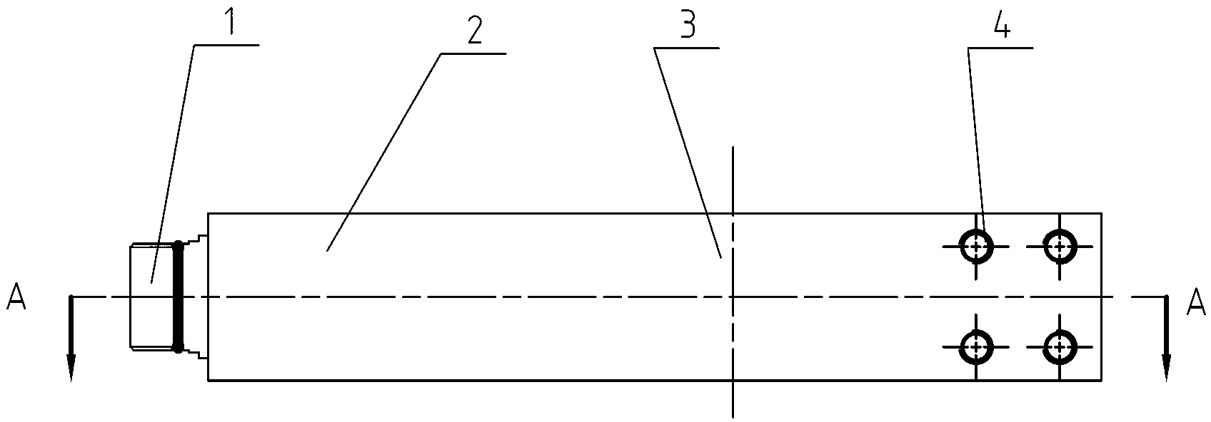
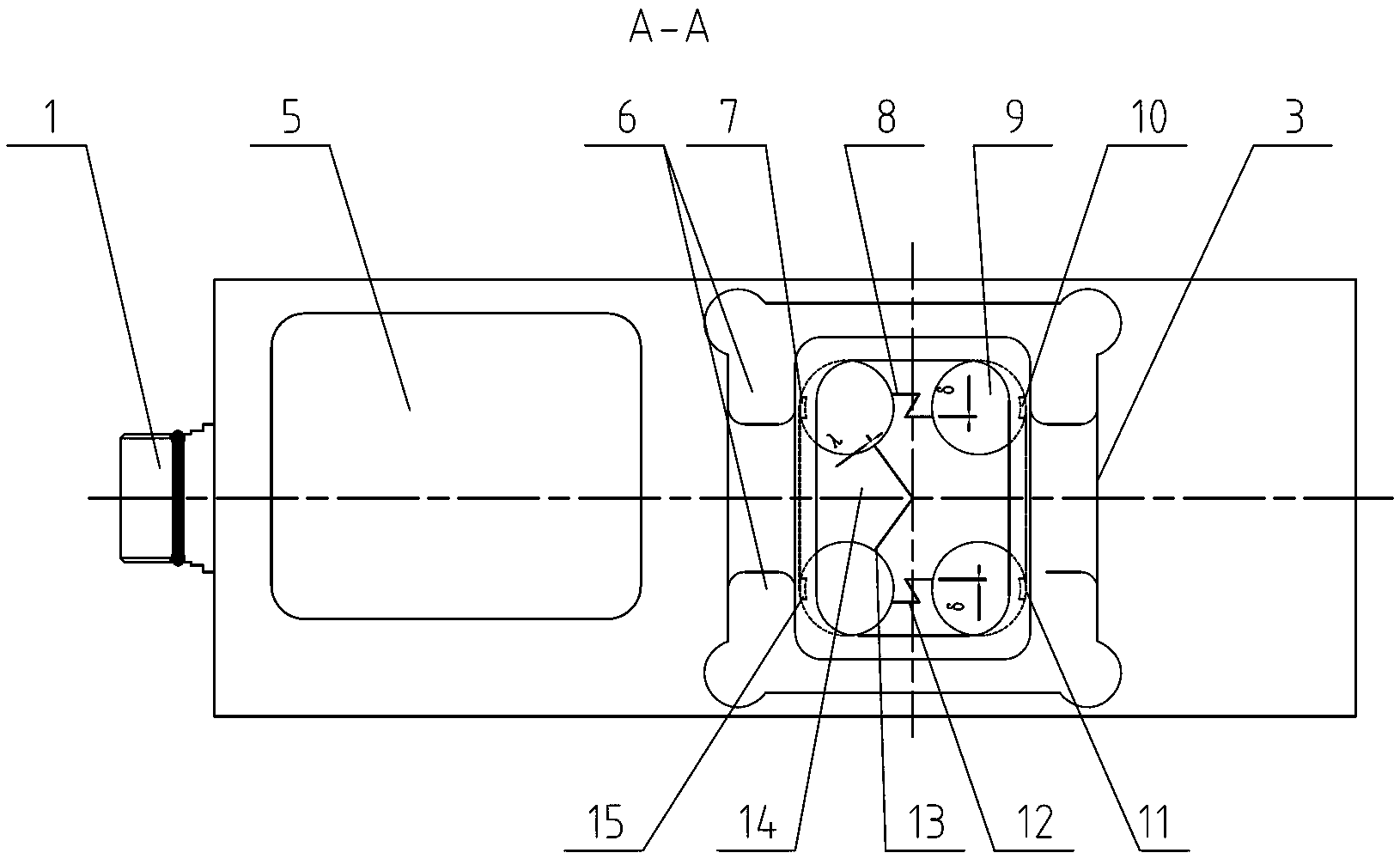
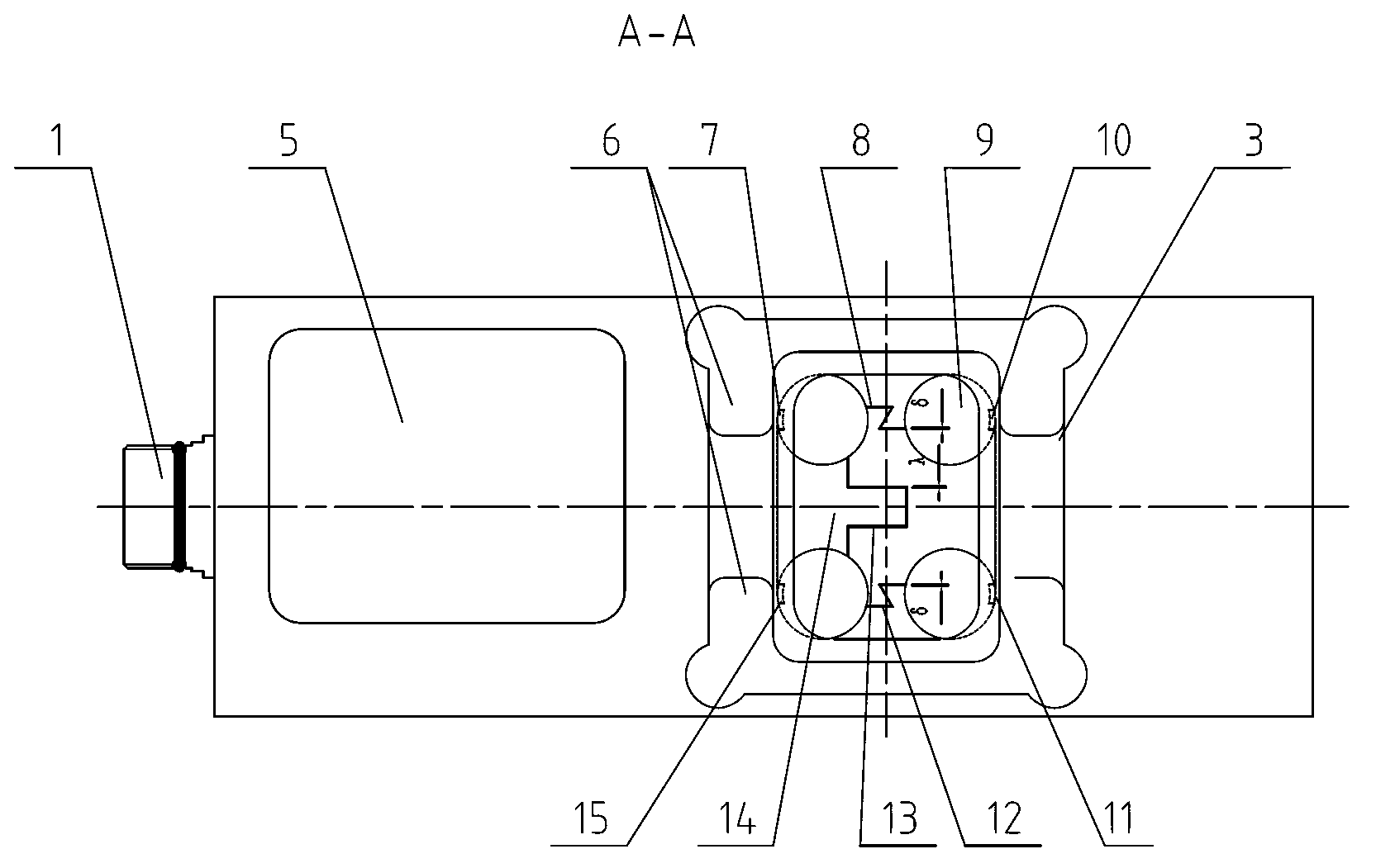
[0017] See Figure 1~4 As shown, the elastic body of the load cell of the present invention includes a fixed part 2 and a strain part 3. The fixed part 2 includes a printed board installation hole 5 arranged on the elastic body, and a printed board is installed in the printed board installation hole 5. The printed board is connected with the cable connector 1, and the electrical signal is output through the cable connector 1. The fixing part 2 also has a threaded hole, and the elastic body is fixed on the base through a fastener. The strain part 3 of the present invention comprises a strain hole 9 on the elastic body and a group of strain gauges fixed in the strain hole 9, a group of strain gauges usually adopts four strain gauges, and each strain gauge is located at the thin wall of the strain hole 9, when When the elastic body is deformed by external force, the strain gauges fixed on the elastic body are also deformed at the same time, causing the resistance value of the str...


PUM


Abstract

The invention relates to an elastic body of a weighing sensor. The elastic body comprises a fixed part and a strain part. The fixed part comprises a printing plate mounting hole formed in the elastic body. The strain part comprises a strain hole formed in the elastic body and a set of strain pieces fixed in the strain hole. A cross-shaped overload beam is arranged in the strain hole. An upper overload gap on an upper groove opening of a vertical beam of the overload beam is used for balancing an output signal during overloading of a first strain piece and a second strain piece on two sides of the upper groove opening. A lower overload gap on a lower groove opening of the vertical beam of the overload beam is used for balancing an output signal during overloading of a third strain piece and a fourth strain piece on two sides of the lower groove opening. The upper overload gap delta 1 of the upper groove opening is identical to the lower overload gap delta 2 of the lower groove opening. A middle groove opening is formed in a horizontal beam of the overload beam. A middle overload gap lambada of the middle groove opening is used for overload protection. The elastic body of the weighing sensor is compact in structure, an overload part is arranged in the elastic body, good side-loading-resistant capacity and good overload protection performance are achieved, controlling and machining are convenient, and service life can be prolonged.

Description

technical field [0001] The invention relates to an elastic body of a weighing sensor, which belongs to the technical field of electronic weighing instruments. Background technique [0002] In industrial occasions, with the continuous improvement of production efficiency, the requirements for weighing are getting higher and higher. Traditional static weighing can no longer meet the high-speed and high-efficiency requirements of modern industry. It is urgent to solve the problem of high-precision weighing in dynamic occasions. . In dynamic situations, the load cell will be affected by more vibration, impact, extrusion, torsion, etc. [0003] With people's attention to food hygiene, the requirements for dynamic weighing technology are getting higher and higher. Under dynamic application, the load cell is required to have high anti-overload capability. Furthermore, due to the particularity of the food industry, it is required that the load cell is easier to clean to meet the ...

Claims


Application Information

Patent Timeline
Patent Type & Authority Applications(China)
IPC IPC(8): G01G21/00
Inventor 王伟郝德刚汤友岸
Owner METTLER TOLEDO CHANGZHOU PRECISION INSTR
Learn More