
Automatic page turning scanner

An automatic page-turning and scanning machine technology, applied in bookmarks, printing, electrical components, etc., can solve the problems of page-turning accuracy, stability impact, uneven rubbing force, and inability to rub the pages, so as to avoid the confusion of the pages. , to achieve automatic page turning, easy to fix effect

Inactive Publication Date: 2013-08-21
ZHENGZHOU UNIV
View PDF4 Cites 14 Cited by
  • Summary
  • Abstract
  • Description
  • Claims
  • Application Information

AI Technical Summary

Problems solved by technology

Although this product can barely achieve automatic page-turning scanning, it still has the following defects: ① The height of the book-rubbing probe will not change with the number of pages turned, and the strength of book-rubbing is not constant, which will easily cause the book to be rubbed when there are few pages in the later stage. The problem of not getting up; ②According to the accompanying drawings figure 2 As shown, the positioning block can only fix the page to be turned, and there is no fixing device for the page that has been turned, which is prone to the problem of affecting the scanning effect due to the page reply; figure 2 It is speculated that the book-turning track of the book-turning probe is based on the coupling as the center to draw an arc-shaped upward flip. Since the book-turning probe cannot always stick to the root of the page, when the book-turning probe reaches the highest point, the page is prone to slipping, causing the page to turn Failed; ④ When the book-turning probe repeats the next page-turning action, it needs a telescopic stepping motor to move it back and forth, reverse and then stretch out. The action steps are complicated and affect the efficiency of page-turning
The above defects affect the accuracy and stability of page turning, and are prone to missing and random turning problems

Method used


Image

  • Automatic page turning scanner
  • Automatic page turning scanner
  • Automatic page turning scanner

Examples


Embodiment Construction

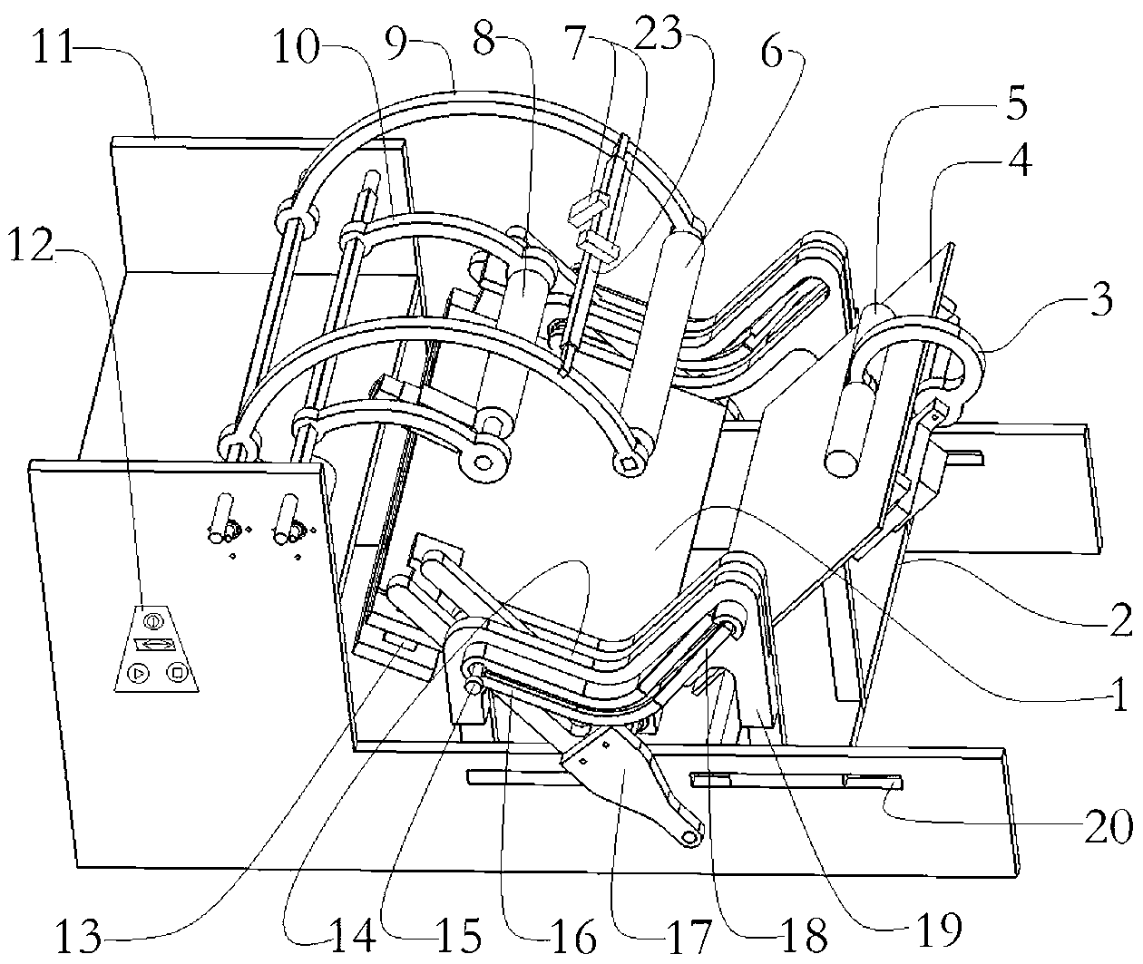
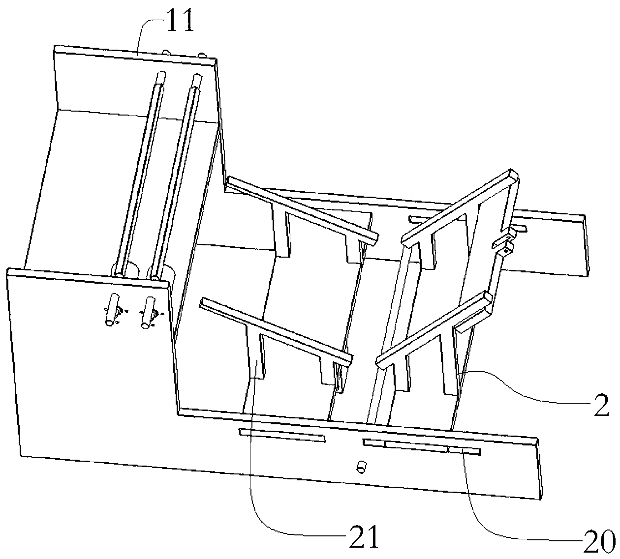
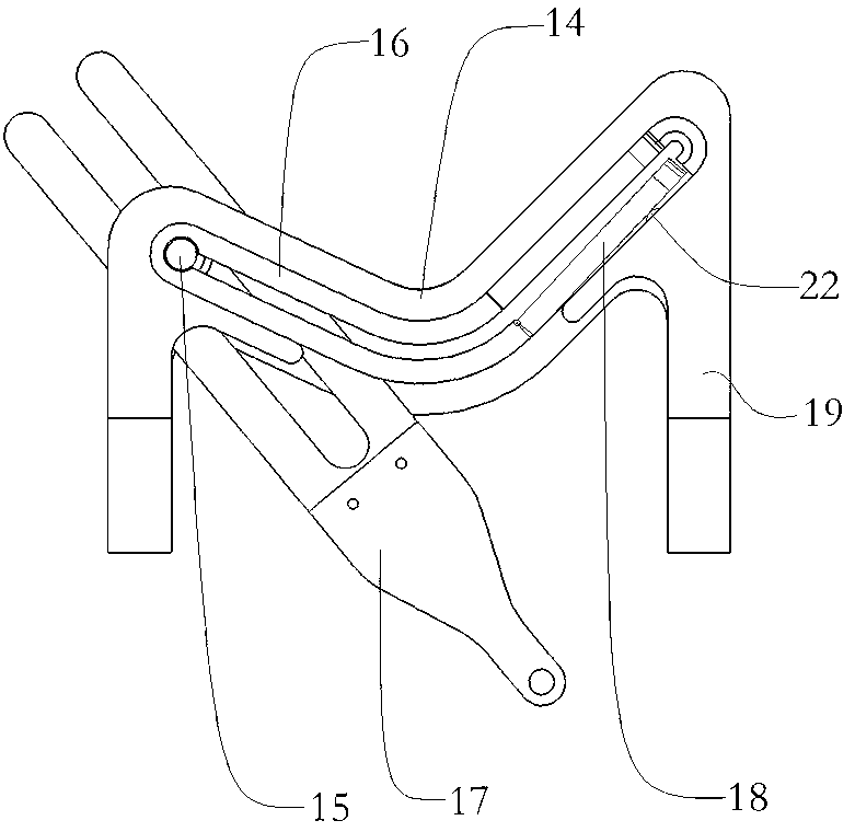
[0021] See also attached Figure 1-4, the structure of a specific embodiment of the present invention includes a frame 11, the frame 11 is provided with a fixing device, a page turning device, a scanning element 7, a control system and an operation panel 12, and the fixing device includes fixing by a fixed frame 21 The workbench I1 set on the frame 11, the workbench II4 set on the frame 11 through the sliding frame 2, the page edge clip 13 set on the workbench I1, are movably connected to the machine through the pick rod 9. The presser hand I6 on the frame 11 and suspended above the workbench I1, the arc bar 3 movably connected to the back of the workbench II4, and the presser hand II5 connected to the arc bar 3 and suspended above the workbench II4, said The sliding frame 2 is movably arranged in the chute 20 on the side wall of the frame 11 and is controlled by the motor I. The angle between the workbench I1 and the workbench II4 is 150°, and it is connected to the V-shaped ...


PUM


Abstract

The invention discloses an automatic page turning scanner which comprises a rack. A fixing device, a page turning device, a scanning element, a control system and an operation panel are arranged on the rack. The fixing device comprises a workbench I, a workbench II, a margin clamp arranged on the workbench I, a pressing hand I and a pressing hand II, wherein, the pressing hand I and the pressing hand II are used for pressing a book. The page turning device comprises a V-shaped rail, a swinging fork, a shifting rod and a page rubbing wheel. A beam is arranged on a take-up lever. The scanning element comprises two cameras arranged on the beam and the cameras are connected with a memorizer. The control system comprises a single chip microcomputer, a motor set controlled by the single chip microcomputer and a switch circuit of the margin clamp. The automatic page turning scanner can achieve automatic page turning, scanning and storage and improve automatic level for binding book printing. Compared with a product of the same type, the automatic page turning scanner has the advantages of being accurate in page turning, high in stability and capable of avoiding the problems of page turning omission and page turning disorder.

Description

technical field [0001] The invention relates to an automatic page-turning scanning machine, in particular to a device for automatically turning pages and scanning for binding paper. Background technique [0002] Scanning is a necessary prerequisite process for copying documents. Generally, copiers can automatically feed, scan and copy unbound paper one by one. However, for bound paper, it needs to be manually scanned and copied one by one, or disassembled into a single Scanning and copying sheets, the work efficiency is low, and the operation process is cumbersome. [0003] In response to the above problems, some products that can automatically turn pages and scan have appeared. For example, Chinese patent 200510028676.2 discloses an automatic page-turning scanner, which includes: a scanning module, an image processing and transmission module, a user interface module, a storage Module, computer interface module, main controller module, battery and power management module,...

Claims


Application Information

Patent Timeline
Patent Type & Authority Applications(China)
IPC IPC(8): H04N1/04B42D9/04
Inventor 张峥赵新灿裴东杰任怡秦营周张东坤马栋栋周晓伟
Owner ZHENGZHOU UNIV
Learn More