Fuel injection valve
A fuel injection valve and fuel technology, which can be used in fuel injection devices, charging systems, machines/engines, etc., to solve problems such as spray deterioration and fuel fluctuations
- Summary
- Abstract
- Description
- Claims
- Application Information
AI Technical Summary
Problems solved by technology
Method used
Image

Examples
Embodiment 1
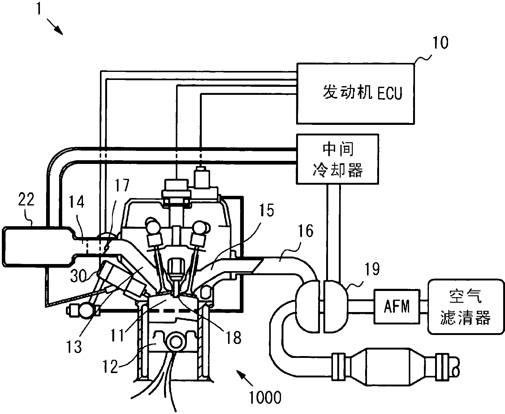
[0051] Embodiment 1 of the present invention will be described with reference to the drawings. figure 1 It is a figure which shows a structural example of the engine system 1 equipped with the fuel injection valve 30 of this invention. In addition, in figure 1 Only a part of the structure of the engine 1000 is shown in FIG.
[0052] figure 1 The illustrated engine system 1 has an engine 1000 as a power source, and an engine ECU (Electronic Control Unit, electronic control unit) 10 that collectively controls the operation of the engine 1000 . Engine system 1 has fuel injection valve 30 that injects fuel into combustion chamber 11 of engine 1000 . The engine ECU 10 has the function of a control unit. The engine ECU 10 is equipped with a CPU (Central Processing Unit, Central Processing Unit) for performing calculation processing, a ROM (Read Only Memory, Read Only Memory) for storing programs, etc., a RAM (Random Access Memory, Random Access Memory) for storing data, etc., N...
Embodiment 2
[0078] Next, refer to Figure 7 Example 2 will be described. Figure 7 It is an explanatory diagram showing the tip portion of the fuel injection valve 50 according to the second embodiment. The basic structure of the fuel injection valve 50 is the same as that of the fuel injection valve 30 of the first embodiment. That is, the fuel injection valve 50 includes a nozzle body 51 , a needle 52 , an injection hole 53 and a seat 54 . In addition, a fuel introduction passage 56 is formed in the fuel injection valve 50 . In addition, the fuel injection valve 50 is also the same as the fuel injection valve 30 in that it includes the swirling flow generation portion 52 a and the spiral groove 52 b. The fuel injection valve 30 and the fuel injection valve 50 differ in the following points. That is, the shape of the turning speed increasing portion 55 is different from that of the turning speed increasing portion 35 . The inner peripheral wall surface of the rotation speed-up part ...
Embodiment 3
[0080] Next, refer to Figure 8 Example 3 will be described. Figure 8 It is an explanatory diagram showing the tip portion of the fuel injection valve 70 of the third embodiment. The basic structure of the fuel injection valve 70 is the same as that of the fuel injection valve 30 of the first embodiment. That is, the fuel injection valve 70 includes a nozzle body 71 , a needle 72 , an injection hole 73 and a seat 74 . In addition, a fuel introduction passage 76 is formed in the fuel injection valve 70 . In addition, the fuel injection valve 70 is also the same as the fuel injection valve 30 in that it includes the swirling flow generating portion 72 a and the spiral groove 72 b. The fuel injection valve 30 differs from the fuel injection valve 70 in the following points. That is, the shape of the turning speed increasing portion 75 is different from that of the turning speed increasing portion 35 . The inner peripheral wall surface of the rotation speed-up part 35 is as ...
PUM
 Abstract
Description
Claims
Application Information
 - R&D
- Intellectual Property
- Life Sciences
- Materials
- Tech Scout
- Unparalleled Data Quality
- Higher Quality Content
- 60% Fewer Hallucinations
Browse by: Latest US Patents, China's latest patents, Technical Efficacy Thesaurus, Application Domain, Technology Topic, Popular Technical Reports.
© 2025 PatSnap. All rights reserved.Legal|Privacy policy|Modern Slavery Act Transparency Statement|Sitemap|About US| Contact US: help@patsnap.com